@Khron
N27 core with 22 Turns at primary of current sense transformer
Does this core do the job B64290L0045X027 from EPCOS https://www.distrelec.de/ishop/Datasheets/B64290-L45-X27_ger.pdf ?
That looks cool.
It will do the Job
Other materials will work also, if you have some used cores it can be used also
You are using an out of date browser. It may not display this or other websites correctly.
You should upgrade or use an alternative browser.
You should upgrade or use an alternative browser.
1kW smps project (based on MicrosiM design)
- Thread starter ludo3232
- Start date
Cores and power
What? +-80VDC @ 25 AMPS? thats 4000W SMPS
That SMPS will give you 1100W long term constant, 1600 for short term, (what they call music terms)
Also, I am planing to make a crazy SMPS in the near future with two ETD59 + PFC on same PCB!!
If you are looking for that power, Its not possible with that SMPS you will need some thing bigger, in the mean time you can make it if you wish.
or two of that SMPS will give you 2400W RMS of output and 3200W PEAK
Regarding cores, If you can GET N87 Core, Ludo found it better than N87. but BOTH will work
Thank you
What was the other?Regarding cores, If you can GET N87 Core, Ludo found it better than N87. but BOTH will work
luchni
New member
Pcb
So, i am 80% done with redrawing ludo's PCB for this SMPS, only have to add the fast diodes and capacitors. The protection card PCB is completely redrawn, and i'm planning to fit it on the main PCB because it will be simpler to make it (one PCB instead of two). Only problem is i have to shorten the protection PCB for 20mm as it is now 32x80mm and then it will fit, i'll move some elements around for the best fit. I won't share the .brd file, i will only give the pdf version.
For now i won't draw any other versions, as in my mind this is the simplest design for the PCB (great job ludo3232 ), if i do another design, i'll post here.
And two questions:
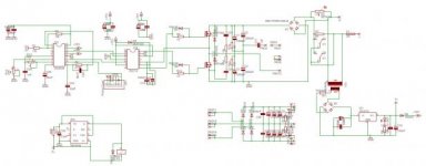
1. Where on the schematic do the 'current sense' leads from the PCB in the attachment hook up to?
2. What is the use of the jumper connected to the 1uF capacitor and one lead from the ETD49 transformer? Is it necessary for something, or can i draw the PCB without it?
Edit: sorry for small thumbnail, but you all have the schematic, so no problem
So, i am 80% done with redrawing ludo's PCB for this SMPS, only have to add the fast diodes and capacitors. The protection card PCB is completely redrawn, and i'm planning to fit it on the main PCB because it will be simpler to make it (one PCB instead of two). Only problem is i have to shorten the protection PCB for 20mm as it is now 32x80mm and then it will fit, i'll move some elements around for the best fit. I won't share the .brd file, i will only give the pdf version.
For now i won't draw any other versions, as in my mind this is the simplest design for the PCB (great job ludo3232
), if i do another design, i'll post here.And two questions:
1. Where on the schematic do the 'current sense' leads from the PCB in the attachment hook up to?
2. What is the use of the jumper connected to the 1uF capacitor and one lead from the ETD49 transformer? Is it necessary for something, or can i draw the PCB without it?
Edit: sorry for small thumbnail, but you all have the schematic, so no problem
Attachments
Last edited:
And two questions:
1. Where on the schematic do the 'current sense' leads from the PCB in the attachment hook up to?
2. What is the use of the jumper connected to the 1uF capacitor and one lead from the ETD49 transformer? Is it necessary for something, or can i draw the PCB without it?
If you had read the last two or three pages of this thread (and looked at ludo's prototype photos), you'd know already
1. Those two leads go to the secondary of the current transformer
2. That jumper is the "primary" of the above-mentioned current transformer -)
Thanks
I am not after credit from that forums. Or we made SMPS to get credit from them.
its more than enough for me the people interested into this place and into this SMPS.
It may look little interest, but I am so happy with that. and will give any one here support to the last minute.
Regarding your ETD49. what you have on hand? or what you can get?
Thanks
Ludo ..! would be nice to comment on this forum, you deserve your credit and that of microsim too .. good job, I can not find etd49 in my country ... greetings from mexico..
I am not after credit from that forums. Or we made SMPS to get credit from them.
its more than enough for me the people interested into this place and into this SMPS.
It may look little interest, but I am so happy with that. and will give any one here support to the last minute.
Regarding your ETD49. what you have on hand? or what you can get?
Thanks
New PCB
I welcome a new PCB layout :UP: thats very nice from you indeed.
This will make it more flexible.
Please Show a snap shot of your PCB.
You can keep the eagle files with you, while you will supply the necessary PDFs for members to make there own PCBs.
Thanks
So, i am 80% done with redrawing ludo's PCB for this SMPS, only have to add the fast diodes and capacitors. The protection card PCB is completely redrawn, and i'm planning to fit it on the main PCB because it will be simpler to make it (one PCB instead of two). Only problem is i have to shorten the protection PCB for 20mm as it is now 32x80mm and then it will fit, i'll move some elements around for the best fit. I won't share the .brd file, i will only give the pdf version.
For now i won't draw any other versions, as in my mind this is the simplest design for the PCB (great job ludo3232
And two questions:
1. Where on the schematic do the 'current sense' leads from the PCB in the attachment hook up to?
2. What is the use of the jumper connected to the 1uF capacitor and one lead from the ETD49 transformer? Is it necessary for something, or can i draw the PCB without it?
Edit: sorry for small thumbnail, but you all have the schematic, so no problem
I welcome a new PCB layout :UP: thats very nice from you indeed.
This will make it more flexible.
Please Show a snap shot of your PCB.
You can keep the eagle files with you, while you will supply the necessary PDFs for members to make there own PCBs.
Thanks
terminaterx300
New member
i have a question about thickness and width of copper layer for high power SPMS. normal its thickness is 2 Oz ~ 0.035mm.and how we calculate the width of copper layer
luchni
New member
Aaaahh, now i get it, sorry Khron, i wasn't reading closely.
I was confused a bit but then, like you said, i looked at the early versions of the PCB and parts placement and ludo3232's final prototype. On the prototype picture he posted on page 10 i saw the little silver-looking thing and re-read your comment and everything was clear to me :UP::UP::UP:
I'll post the picture of the PCB today, maybe even the final version tonight.
i have a question about thickness and width of copper layer for high power SPMS. normal its thickness is 2 Oz ~ 0.035mm.and how we calculate the width of copper layer
Dont forget to make 3mm margin from both sides of bobbin, if you will use Cooper foil.
Cooper foil is very good for SMPS application, specially in the range of 100KHZ and above.
terminaterx300
New member
Dont forget to make 3mm margin from both sides of bobbin, if you will use Cooper foil.
Cooper foil is very good for SMPS application, specially in the range of 100KHZ and above.
no,i want to ask about copper layer of pcb when we design layout. any rule such as 5A : line not less then x mm wide with 0.035 mm thick copper
p/s if i cant find copper foil tape,could i replace with alu tape
luchni
New member
Looking through my junk stuff i found the T50 toroid for the current transformer (kinda green-gray color with a blue ring painted on one side). I did a little research and found out that for this smps it's best to use T50-3 type core for the current transformer. The ferrite core calculator i found doesn't have the color combination or color (which marks the material type) of my toroid, so (assuming the calc is right) can this core be used for this smps?
http://www.66pacific.com/calculators/toroid_calc.aspx
http://www.66pacific.com/calculators/toroid_calc.aspx
no,i want to ask about copper layer of pcb when we design layout. any rule such as 5A : line not less then x mm wide with 0.035 mm thick copper
p/s if i cant find copper foil tape,could i replace with alu tape
for 1100W SMPS, you can use the 0.035mm PCBs, ALSO cooper foil IS not required if you are using wires! (Strands)
I advice all, to start step by step, showing & asking here to have success from first time
Thanks for all
