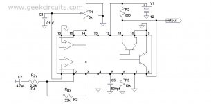
Here's my d3k amp.It sound's good.No hiss or noise in speaker.Output DC max +/-15mV
It use separated and isolated gate drive which is recommended for high powers.It can operate from +/-6 to +/-120V.For higher than +/-120V there's another circuit but it's almost not needed that high power.
Working frequency is 100kHz.I use TL494 because it's good,cheap and reliable.I don't like amp's with varying frequency.For optocouplers I use 6N137,which is at least double faster than IR2110.Output fet's can be any which have enough voltage and current rating.Amp is very powerfull.I don't upload pictures because I made it in 3D way.When I get pcb,I'll attach pics here.duty cycle can vary from 0 to about 90% or more,depend on TL494.It means that this amp has more power than UcD one,because UcD has smaller duty deviation.
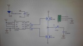
This is tested on +/-25 and +/-50 and soon will be tested on +/-70 and +/-100V.It will work with any voltage up to +/-120V.Load can be 4 or 8 ohm,or even smaller loads like 1 ohm,but with bigger Fet's.It can be used as car amp too,where low dissipation and long batery life is needed.Output inductor is E33,and I'll calculate gap and number of turns for power that You need.For tests I use E33,gap 1,5mm betwen core halfs and 40 turns taped on half (20 turns used up to +/-35V).Use two separated 12-15V supplies for gate drive.For test you can use bootstrap circuit located on schematic.With this,you need only one 12V supply (between 12V_2 and 0V_2).But this is only for tests.For high power it's recommended to use separated gate drive.Dead time provided by pull up 220R resistor.You can use 100R,but it will heat more and output Fet's maybe will heat more.For resistors providing +/-8V for controller it's calculated R=U[one rail voltage]/0,04. For C15 I use 1uF.
PCB diensions is 100x80mm
If You have any questions ask freely.
There's PCB,and schematic.Pictures when I get pcb


View attachment d3k opto bot..pdf
It use separated and isolated gate drive which is recommended for high powers.It can operate from +/-6 to +/-120V.For higher than +/-120V there's another circuit but it's almost not needed that high power.
Working frequency is 100kHz.I use TL494 because it's good,cheap and reliable.I don't like amp's with varying frequency.For optocouplers I use 6N137,which is at least double faster than IR2110.Output fet's can be any which have enough voltage and current rating.Amp is very powerfull.I don't upload pictures because I made it in 3D way.When I get pcb,I'll attach pics here.duty cycle can vary from 0 to about 90% or more,depend on TL494.It means that this amp has more power than UcD one,because UcD has smaller duty deviation.
This is tested on +/-25 and +/-50 and soon will be tested on +/-70 and +/-100V.It will work with any voltage up to +/-120V.Load can be 4 or 8 ohm,or even smaller loads like 1 ohm,but with bigger Fet's.It can be used as car amp too,where low dissipation and long batery life is needed.Output inductor is E33,and I'll calculate gap and number of turns for power that You need.For tests I use E33,gap 1,5mm betwen core halfs and 40 turns taped on half (20 turns used up to +/-35V).Use two separated 12-15V supplies for gate drive.For test you can use bootstrap circuit located on schematic.With this,you need only one 12V supply (between 12V_2 and 0V_2).But this is only for tests.For high power it's recommended to use separated gate drive.Dead time provided by pull up 220R resistor.You can use 100R,but it will heat more and output Fet's maybe will heat more.For resistors providing +/-8V for controller it's calculated R=U[one rail voltage]/0,04. For C15 I use 1uF.
PCB diensions is 100x80mm
If You have any questions ask freely.
There's PCB,and schematic.Pictures when I get pcb
View attachment d3k opto bot..pdf
Last edited: