You are using an out of date browser. It may not display this or other websites correctly.
You should upgrade or use an alternative browser.
You should upgrade or use an alternative browser.
EI-33 based half bridge
- Thread starter zeus_threat
- Start date
zeus_threat
Member
Hi Microsim, thanks for the reply. Well actually my isolated transformers were very stable its paralleling lamps as load that cause issues. It seems better to uses a single 200W lamp as load than parallel 4X50W to reach the same figure. Just a quick questions have you ever tried to use 200W or 500W halogen lamps as load instead of basic 220V light bulbs?
Hi Microsim, thanks for the reply. Well actually my isolated transformers were very stable its paralleling lamps as load that cause issues. It seems better to uses a single 200W lamp as load than parallel 4X50W to reach the same figure. Just a quick questions have you ever tried to use 200W or 500W halogen lamps as load instead of basic 220V light bulbs?
I tried that in the past, but its not recommended. Lamps will act like short circuit when you connect to the SMPS.
I am very interested into your AUX SMPS supply, becaause I am also working on same thing, I have success with LNK306 chip , drawn 16V 300MA witch is perfect to run every thing on the SMPS. but its not isolated! !!!:
Bulbs will work as load, but I don't advice you to use them.
zeus_threat
Member
hi Microsim thanks for the reply. I have looked around a little bit about possible solutions for the ic bias startup:
1) Linear regulator simple to use but not isolated it also requires bulky resistors.
2) Buck converter non isolated only 1 coil to wind but i need to find an ic that can operate straight from 320V dc maybe VIPER or TOP ic's i have to take a look otherwise a power resistor will be needed to drop the voltage for the buck ic. Another factor seems to be the fact that they will operate on
very low duty cycle
3) Flyback popular isolated solution but i have already had my time with these though they are heavily used in cellphone chargers dvd/bluray players but getting the right core is a little bit tough and its building another smps to supply another one though once done its done for all no need to r&d on it.
4) Self oscillating half bridge these are the only implemented solutions in CFLs though CFLs are not isolated by their nature i think the solution could be extended or re-enginnered. The only issue is the proportional base drive which is annoying
5) Power resistor to drop 320Vdc to supply ic for start up and then get removed. Relay n/o could connect power resistor to 320Vdc, drop to 15V for 20ms or so and when the smps starts the relay disconnects the resistor. Its actually the simplest of all solutions i could think of.
Besides what i did mention up there is also another point which is i am aiming at building a "supply bias start up" my auxiliary supply is found in my main transformer the "bias start up supply " i am aiming to build is mainly to ge tthe smps started and get switched off afterwards.
Its already wound on my current EI-33 transformer and giving a higher than needed voltage to cater for voltage drops when the main secondary will be loaded. I prefer this solution as its more efficient than have an auxiliary supply contantly running.
I'll see which of the 5 solutions comes more handy or another one i might not have though of. What i am looking for is a repeatable solution that once working it can be implemented in any smps i intend to build
If you have any additional thoughts you want to share am open to discussion i will also have a look at the ic that you have mentionned.
AUX Supply
Hi Zeus
Yes, things not that easy
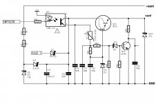
But you can take a look at the attached circuit, and you can make some tests
For commercial use, I plan to use TOP242 chip with EE16 core that will give 300ma 16Vdc to power every thing.
as DIY you can try that circuit, I have another one also
Both from commercial amplifiers, Enjoy!

zeus_threat
Member
Possible bias startup
Thanks for the circuit microsim. I will try to simplify and simulate it. Most of the diy options revovle around series pass regulator. If you have another circuit i will be glad to have a look at it. I also came across this following app note while searching on the floating regulator side still based on the series pass transistor acting as pregulator followed by a lm317 http://www.national.com/ms/LB/LB-47.pdf
My bias startup will have to conduct for more than 470Ns and less than 1 sec before the smps is fully up and running which is roughly the time the TL494 soft start kicks in and the mosfet begin to conduct.
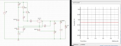
This is the schematic and power dissipation in the transistor the devices are for simulation only the devices i will use will have a higher Vce or i will go for a tip122 : What do you think?
I could even couple that with an optocoupler to switch off the circuit when the smps goes active
Thanks for the circuit microsim. I will try to simplify and simulate it. Most of the diy options revovle around series pass regulator. If you have another circuit i will be glad to have a look at it. I also came across this following app note while searching on the floating regulator side still based on the series pass transistor acting as pregulator followed by a lm317 http://www.national.com/ms/LB/LB-47.pdf
My bias startup will have to conduct for more than 470Ns and less than 1 sec before the smps is fully up and running which is roughly the time the TL494 soft start kicks in and the mosfet begin to conduct.
This is the schematic and power dissipation in the transistor the devices are for simulation only the devices i will use will have a higher Vce or i will go for a tip122 :
 What do you think?
I could even couple that with an optocoupler to switch off the circuit when the smps goes active
Last edited:
zeus_threat
Member
After a lot of searching i think i'll go for a single series pass high voltage npn with collector limiting resistor. It will take up some space but nevermind as long as i can get rid of those auxiliary transformer
zeus_threat
Member
Its working!!!!
I got it to work and it starts up great with the bias startup using series pass transistor. Its a grown up independent smps now lol But there is one only thing i need to implement a form of protection that in case the smps does not start up the bias does keep running continously. maybe an rc circuit would do. And guess what guess what guess what i've pushed the SMPS components recycling further
  how??????? My series pass is nothing more than those MJ13007 you get in those pc based smps. Great huh?
I got it to work and it starts up great with the bias startup using series pass transistor. Its a grown up independent smps now lol
zeus_threat
Member
Bias startup circuit
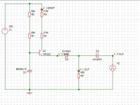
This is the bias startup circuit i have used for the TL494: . Like i said it needs to be switched off after some time to avoid overdissipation which has to be implemented. The transistor is really cool disspating only a few milliwatts. The 68K heat up a bit but the 7.5K do get very hot. I'll see what i come up to as a switch circuit after x seconds. In terms of cost this circuit is is cheaper than a transformer but the ic is then on the primary side on live ground. In case regulation has to be applied it will need isolation with optocoupler. This will be next step after i complete the protection for bias startup
This is the bias startup circuit i have used for the TL494:
 . Like i said it needs to be switched off after some time to avoid overdissipation which has to be implemented. The transistor is really cool disspating only a few milliwatts. The 68K heat up a bit but the 7.5K do get very hot. I'll see what i come up to as a switch circuit after x seconds. In terms of cost this circuit is is cheaper than a transformer but the ic is then on the primary side on live ground. In case regulation has to be applied it will need isolation with optocoupler. This will be next step after i complete the protection for bias startup
Zeus
This maybe of interest to you!
Another simple SMPS, Hope it will help you
this thing work? how much power it can deliver? Though its very simple circuit lol
zeus_threat
Member
Hi noramzi go to the second page of my post the oscillator schematic is there you just need to send op1 and op2 to your GDT transfromer primary and replace the 1uf cap with a 10R resistor. Yes that startup circuit works very well its only to bias the ic and the system runs from secondary vaoltage all the time the ic does not need any auxiliary transformer. Like i said i still need to implement a switch off protection for the startup bias. It also not yet on pcb as well as my first TL494 SMPS. One good advice before you start on this project measure your EI33 core al values this link exlpains how to do it: http://wiki.4hv.org/index.php/Gate_drive_transformer mine has an AL >3000 and i had to throw away 3 other EI-33 core before i got a proper one.
The GDT core is also very tricky in this design i have used two cores with AL=2800 to reach an AL above 4000. this guide has a table about required inductance for GDT cores:http://www.ferroxcube.com/news/gate drive trafo.pdf. If you don't have an inductance meter and oscilloscope this project is going to become a real nightmare.
Just for info i built this to get around 200-250W peak power and 150W continuous during normal use.
Last edited:
zeus_threat
Member
hi yes there is protection same as in my first TL494 smps using current sense transformer already mentionned in this here when i was doing testing
zeus_threat
Member
Everything you need to know is in this thread http://www.diysmps.com/forums/showthread.php?158-Drive-signal-issues-with-half-bridge go through it
zeus_threat
Member
Hi really sorry for the looooong wait for the reply i was very busy and got so much into microcontrollers microchip v/s Arm and all the pic features took a lot of my time plus rebuilding my pcb exposure box to use UV leds and a 16F628A timer that was in the land of stack interrupt.... My supply works very well and the smps worked like a charm with the Aux start up. I have tested the SMPS for continuous switch on and switch off and it managed to survive unstable lamp loads easily without blowing up. The double AL core method solved a lot of problems i need to buy more of these CFL lamps to keep their cores for further projects. I haven't had time to build the switch off circuit yet but i will attempt it as i get some time. One idea comes to my mind anyone built electronic loads controlled by microcontrollers before???? I saw low power versions but if you beef it up with a rotary encoder ,an LCD and well programmed with the microcontroller ADC/Comparator....... no more lamps
Last edited:
