You are using an out of date browser. It may not display this or other websites correctly.
You should upgrade or use an alternative browser.
You should upgrade or use an alternative browser.
Class D 200 Wrms with 2 mosfet cheap
- Thread starter norazmi
- Start date
The speaker is 4Ohm, but this shouldn't be the problem since the core starts to buzz even with nothing connected when clipping to the supply lines. ")
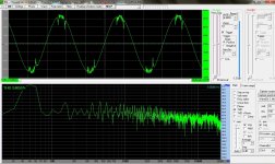
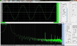
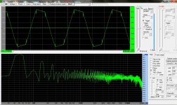
I noticed the buzzing becomes less when i even increase the output clipping (pic).
So i think some harmonics cause the core to vibrate, i will leave it as it is since we all dont listen to music if the amp is clipping? :"::
Have a nice day everyone.
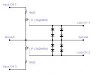
t68kv see the 2nd pic & visit this http://hacca.altervista.org/
I noticed the buzzing becomes less when i even increase the output clipping (pic).
So i think some harmonics cause the core to vibrate, i will leave it as it is since we all dont listen to music if the amp is clipping? :"::
Have a nice day everyone.
t68kv see the 2nd pic & visit this http://hacca.altervista.org/
Attachments
-
 quieter.jpg308 KB · Views: 44
 -
 connect.jpg8.1 KB · Views: 103
Abet i'm using this one from mile: http://www.diyaudio.com/forums/solid-state/162043-mosfet-amplifier-irfp240-irfp9240-48.html
OK thanks, you did a pretty compact build :UP:
hi guys after reading through this post and ultra simple class d i have changed my layout to use bd 1xx transistors instead of 2n 5xxx . so as to make it work normal and reduce heat of output fets . i had made three circuits all i used +/-36vlts and all were heating the out put fets until i added 680r in series with 220r (r9 and r20).
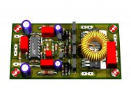
but after hearing the clarity of this amplifier i decided to use the original version which has been simulated by norazmi . here is my layout and artwork . -) -) -)
http://www.diyaudio.com/forums/class-d/205654-ultra-simple-class-d.html reference to the other project
but after hearing the clarity of this amplifier i decided to use the original version which has been simulated by norazmi . here is my layout and artwork . -) -) -)
http://www.diyaudio.com/forums/class-d/205654-ultra-simple-class-d.html reference to the other project
Attachments
-
Class D 200 Wrms with 2 mosfet pcb artwork.pdf2.8 MB · Views: 640
-
Class D 200 Wrms with 2 mosfet pcb top.pdf27.4 KB · Views: 392
-
Class D 200 Wrms with 2 mosfet pcb bottom.pdf22.8 KB · Views: 312
-
Class D 200 Wrms with 2 mosfet schematic .pdf26.2 KB · Views: 488
-
 Class D 200 Wrms with 2 mosfet .jpg248 KB · Views: 206
 -
Class D 200 Wrms with 2 mosfet pcb components full .pdf25 KB · Views: 392
-
Class D 200 Wrms with 2 mosfet pcb components clear .pdf23.6 KB · Views: 404
Last edited:
paskal
New member
azmi, i've finally got my hands on an inductance meter. measured a suitable coil and found that it's 22uh. but with 1uf cap i get 130mV of dc offset. any idea on how to reduce the offset?Nomad what speaker impedance ? Load 8 ohm speaker, i would like to suggest u do 37 uh with 560nf filter caps, lower load such as 4 ohm u can do 22 uh (awg17) + 1uf cap.
i'm using BD139/BD140 pair with 2N5401/2N5551 and IRF540/IRF9540. VCC is at +-35V. speaker is 4 ohm
Load 8 ohm speaker, i would like to suggest u do 37 uh with 560nf filter caps,
Azmi, what do you mean? for 8ohms load, the inductor should be 37uh with 560nf output filter caps??? How do I do this on T106-2 core...how many turns of copper wires???
I'm currently using T106-2 with 40t of AWG#18 copper wires (said to be 22uh) but I'm using 8ohms fullrange speakers, and while in operation it remains very warm all the time. What should be the ideal temperature of the output coil? Does it have to remain cold all the time?
Here's what I discover so far((@ Increasing the no of turns on T106-2 core makes the output FETS hotter, but it does makes the inductor coil cold all the time. Reducing the no of turns on T106-2 core makes the output FETS cold all the time but it makes the inductor core hotter.
My current set-up, for the totem pole, i used 2Ns and BDs/MJEs combination (e.g. 2N5401 to BD140/MJE340) I figure in the original circuit the totem drivers are not in pair, for the BCs the BDs are pretty good higher power replacements and I guess for the MPSAs the MJEs are the better higher power counterparts. However I am not so sure about the stability of my current set-up, but it does seem to work pretty good. It reduces the abnormal heating of 220ohms resistor.
((@((@
TY!
BTW I like the Hi-Fi quality of this amp on fullrange speakers, sounds fantastic!
paskal
New member
my god these amp are fragile. i've burned 4 modules already. the newest one got the power caps blown during sine wave test. never have i blown any power caps (a good one) during my years of amp building. i'm only extracting ~128w from them (into 4 ohm load) playing 35Hz sine wave into one of these (the one on the right)


and poof it goes into smoke after 2 minutes of playback. trying to run in the woofers before mounting them into their enclosure. good thing i have dc protection integrated.
and poof it goes into smoke after 2 minutes of playback. trying to run in the woofers before mounting them into their enclosure. good thing i have dc protection integrated.
can't find any T106-2 bro. so i went ahead with a larger ferrite that i pulled out from the PSU. tried running a trafo from the PSU, but it killed one of my modules. sigh. learning from my mistakes.what type lc filter do you use? T106-2 or ferrite with gap?
huh, T68KV U really need non ucd TL074 with ir2110 for this sub hahahahaha . Dont try hard without mounting output mosfet on heatsink. First test with low volume, play it about 30 mins to 1 hr and second test with medium volume do it with same testing time or more like 2 hrs, at this state u need to check coil temp and output mosfet temp, also check other component that might overheat.
FYI i already build many of this amp, last one i did with car amp, running at +/- 40 vdc and pushing kenwood KFC-W3013 12 " sub without any problem with no overheat or etc.... I did push it hard until car battery drop 11.88vdc from 14.02vdc with engine started. With only 1 channel class D 200wrms the voltage from car drop too much .
please send clear picture of ur amp to my email.
regards.
hahahahaha . Dont try hard without mounting output mosfet on heatsink. First test with low volume, play it about 30 mins to 1 hr and second test with medium volume do it with same testing time or more like 2 hrs, at this state u need to check coil temp and output mosfet temp, also check other component that might overheat. FYI i already build many of this amp, last one i did with car amp, running at +/- 40 vdc and pushing kenwood KFC-W3013 12 " sub without any problem with no overheat or etc.... I did push it hard until car battery drop 11.88vdc from 14.02vdc with engine started. With only 1 channel class D 200wrms the voltage from car drop too much
.please send clear picture of ur amp to my email.
regards.
Last edited:
guys good news i am from listening to this amp it is cold . that is the small sink for fet outputs is so cold and the volume is moderate i used bc327 and bc337 instead of bd139 and 140 .
if you try bc3xx with the layout i posted please don't forget to interchange pins legs .
>>>> my powersupply is +/- 33vlts and outputs are irf9540 and irf540n
earlier i tried 2sa1013 and 2sc2229 (which i have in plenty) but the outputs were hot
if you try bc3xx with the layout i posted please don't forget to interchange pins legs .
>>>> my powersupply is +/- 33vlts and outputs are irf9540 and irf540n
earlier i tried 2sa1013 and 2sc2229 (which i have in plenty) but the outputs were hot
@norazmi
No kidding, mine's playing 15inch 4ohms JBL sub without problem but i have placed one exhaust fan in my small case since the heat is not getting out. In this way, no more heat to any of the parts
@paskal
make sure to check all part for heating and possible breakdown.
In my circuit, the fet's are not heating while to toroid coil heats normal way.
t68kv,
saw your IRS900D post in the thai site, what type of inductor have you used?
paskal,
if you are using the Diego Salas pcb design, you might as well be very careful on the ground wire tap under the board, the wire was so close on one pin of the output fets. I did that mistake while checking any abnormal parts at test and while flipping the board over the exposed wiring must have accidently touch the mosFET pin and presto! I heard a loud bang and one main cap blew up exactly like that in your pic...;ww:::SD