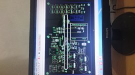
1000w smps based on LUDO3232

Upik

Member
At 60Khz EE65 can deliver 5500w or more. You will need thicker wire in transformer better output diodes and better switching mosfets or IGBTs that can handle 40amps or more. You need to re design the pcb for heavier current in the output. You will need more input and output capacitance.

Regards Silvio

With 5500w Is it capable with HB mr.silvio topology ,, ?? with little change in mosfet and diode., I have 6 capacitor 850uf / 400v on primer. That's what i have. If indeed without changing many original components from schematic, I want to build it. because my Amplifier power is now class d4k5. and pair of d2kneo.seppose both need voltage and current is big enough.
 

Silvio

Well-known member
Hi mr.silvio ,, it looks like ee65 has 2500w power only.

ETD 59 at 20Khz can go to 3000watts at 60Khz can go to can go 4000w. Now EE65 is bigger than ETD 59 so it can go 5000w at 20Khz and more at 60Khz.

You can use Half bridge to 3000w but need 1.5uF per watt across 320v so for 3000w you need 3000 x 1.5 = 4500uF.

Secondary capacitor for 3000w is 6000uF per rail at 60v-0-60v

You need 60 ohms for soft start in input and delay for relay latch 5 seconds

Power IGBT you need 4 X HGTG30N60A4D 2 parallel on each side of half bridge

Aux supply 15v should be strong around 1 to 1.5 amp

What is the secondary voltage that you need?

Silvio
 

Upik

Member
What about igbt 60n60, ??? for secondary voltage 100v every rail, or need 120v any rail for smp which is set. ,, for capacitor divider should be bigger than 2.5uf or maybe same, ???
 

Silvio

Well-known member
What about igbt 60n60, ??? for secondary voltage 100v every rail, or need 120v any rail for smp which is set. ,, for capacitor divider should be bigger than 2.5uf or maybe same, ???

IGBT do not like high frequency so you better make a design for 20Khz This will make it possible to use 0.8mm copper wire
FGH60N60SFD seem ok but must be kept cool as at case temp of 100 deg the power dissipation is half from 370w to 150w .

For divider capacitors use 2X1uF on each side the power is divided between 2 capacitors instead of 1 (there is place for them on my PCB)

Do you know the core material of your EE65 ?

I will make some calculations for winding the transformer for 3KW peak. Please give me bobbin length and also window space

Silvio
 

Upik

Member
Hi mr.silvio ,,, that's what i do not know about that kind of core, i get ee65 not new, but just got from stuff that is not already used.
 

Upik

Member
Well mr.silvio ,, for now i can not give information about dimension ee65,, i am out of town at this time.
 

Silvio

Well-known member
I have combined pwm card and feedback option to be 1 pcb, but resistor DT 120 ohm not working well

I cannot understand you. What do you actually mean by the Dead time resistor not working well.
You need oscilloscope to adjust dead time properly. Is it burning? You have different dead time? Is it VR2 on schematic?
Did you make modification on PWM pcb R7 ( on schematic v2) 1k ohm from pin 1 of SG3525 to HV ground?

If you opted for feedback you must put inductor 15 or 20uH after diode bridge on each rail otherwise it will not work.

You need 20v headroom for regulation on each rail.

Example full peak voltage is 80v then you have to regulate to 60v

Silvio
 

Upik

Member
I have modified pwm, removing 470k and replacing c16 with 100n. Problem is not burning, but why relay works, then die, work and die, like it keep on..is it a problem on ic ne555, ??? for out minus on my feedback connect to graund.
 

Silvio

Well-known member
I have modified pwm, removing 470k and replacing c16 with 100n. Problem is not burning, but why relay works, then die, work and die, like it keep on..is it a problem on ic ne555, ??? for out minus on my feedback connect to graund.

No nothing at all but there must be some load on output otherwise pulse width is too small and +/- 15v will die down to very low volts hence the relay will come off again. One other option is to feed delay circuit separate from direct 15v auxiliary

One other option is to add 1 more turn on the transformer winding so that when pulse width is small there will be enough voltage on the input of the +/-15v regulators 7815 and 7915.

Silvio
 
Last edited:

Upik

Member
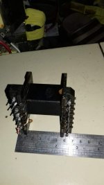
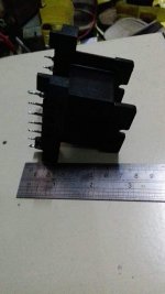
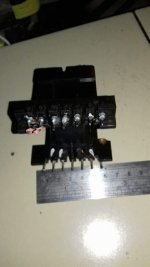
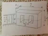
Hi mr.silvio, I want to send the ee65 dimension you are asking.
A=65mm
B=27mm
C=65mm
D=20mm
E=42mm
F=11mm
 

Silvio

Well-known member
Here are some corrections you have to make to pcb.
Press Note at bottom of pdf to see

One other thing you need to use 4 X 20amps fast diodes for secondary output 16amps is small because peak current when charging secondary capacitors will be quite high.

View attachment HB3000W (1) UPIK.pdf

Please tell me the peak secondary voltage of your smps and also if regulated or not. I will give you transformer winding detail later

Silvio.
 
Top