You are using an out of date browser. It may not display this or other websites correctly.
You should upgrade or use an alternative browser.
You should upgrade or use an alternative browser.
1000w smps based on LUDO3232
- Thread starter Silvio
- Start date
Silvio
Well-known member
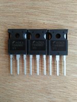
1) IGBT look ok and pin configuration is the same as mosfet
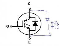
2) MUR460 direct to collector, emitter of IGBT look at my schematic 1000w smps
3) Placement of fuse correct but you can put away from heatsink and components closer together
4) Traces (5-6) make them more strait and parallel.
5)The inductor is not needed for the aux supply as now you have normal transformer not small smps like I had.

Last edited:
Silvio
Well-known member
Transformer winding detail upik
Here is the winding detail in the file below
View attachment UPIK TRAFO.pdf
Here is the winding detail in the file below
View attachment UPIK TRAFO.pdf
Silvio
Well-known member
In the transformer details that I gave you have the volts per turn, now you can adjust turns according to your need. Do not forget that for regulated output you need at least 25 to 30uH inductor on each side of the output. You also need around 25 to 30% more peak voltage to compensate for voltage drop in inductor to get good regulation at high current.
Change also the output diodes, 15A each is not enough you need 20A now as the peak current is higher, You may also need to double IGBT use 4. 2 in parallel on each side of the HB
You also need higher voltage rating capacitors on the output, Be careful and see that peak voltage on secondary does not exceed capacitor voltage because they will not last very long.
You also will need place on pcb for minimum load resistors 5 to 10watts
Good luck Silvio
Last edited:
Silvio
Well-known member
No I do not think you need to add GDT to drive IGBT in parallel as long as the smps works in full duty cycle. The reason is that if the smps has to work with low pulse width then the bootstrap capacitor will not have time to charge properly and problems may arise.
If you are going to use feedback then you have to use GDT for sure switching on the IGBT. Here you have to be careful and see that the switching pulse must be at 12- 15v at all times.
Adding feedback may not be as simple as it seems and if you have no oscilloscope you cannot see what is happening.
I never built an smps with gate drive transformer and I have no detail for it.
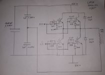
I will add photo of parallel IGBT from home as I have a problem with uploading files from here.
Regards Silvio
Last edited:
Silvio
Well-known member
Sg3525 with ka3525 is same mr.silvio, ??
Yes it is the same
No I do not think you need to add GDT to drive IGBT in parallel as long as the smps works in full duty cycle. The reason is that if the smps has to work with low pulse width then the bootstrap capacitor will not have time to charge properly and problems may arise.
If you are going to use feedback then you have to use GDT for sure switching on the IGBT. Here you have to be careful and see that the switching pulse must be at 12- 15v at all times.
Adding feedback may not be as simple as it seems and if you have no oscilloscope you cannot see what is happening.
I never built an smps with gate drive transformer and I have no detail for it.
I will add photo of parallel IGBT from home as I have a problem with uploading files from here.
Regards Silvio
Well mr.silvio ,, i will leave about feedback. Now i am fixing pcb.
Please check my pcb mr.silvioView attachment HB3000W v2.pdf
Silvio
Well-known member
Please check my pcb mr.silvio
make corrections as marked with red markings. press on them and see note on side
View attachment 6681
regards Silvio
Attachments
Last edited:
Silvio
Well-known member
Hi mr.silvio, i only have some rur3060 diodes and some 30cph03, is that a problem, ??? diode with 2 legs only mur1560 i have
Both diodes are good use what you think fits best. They are a bit over rated though.
Silvio
Well-known member
RUR3060 seems with 30 ampere capability
Yes the part number says so they are 30A (30)and 600v (60)
Silvio
Silvio
Well-known member
Hi mr.silvio ,, if i change the frequency on the pwm card to 25khz, will the DT Resistor be the same, or have to adjust it again, (without feedback)
I know that the dead time will change with frequency but I am not sure which way it will go (smaller or bigger) when you change from a higher frequency to a lower frequency. I understand that you are saying that you leave the same value of resistor that you used at 65Khz.
I am sorry I do not remember this maybe another member can help you here.
Regards Silvio


