Hi all,
this is my first post here and first of all I want to thank you for accept my registration.
My name is Max and I write from Milan, Italy.
Together with a friend we are working since almost 2 years to an open source project for a 200A AC/DC TIG welding machine.
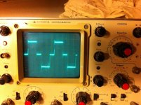
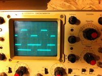
For whom is not familiar with the arc welding this machine have to be capable to deliver 200A of current on the welding torch in DC or AC (square wave) with a frequency adjustable from DC to 250Hz.In the TIG mode there will be an arc starter which uses an HF HV (15KV) oscillator in order to generate a low power high voltage arc which will create the path for the high power low voltage welding arc without scratching the electrode as you normally do in a standard welding machine.
We have planned to built many functions which most of them will be software including unbalanced welding current on the two quadrants when in AC: the current of the positive quadrant can be different from the current of the negative quadrant.
All those functions are needed to solder many different types of metal and thicknesses.
Reading some of the posts in this forum I assume that you guys are more related to audio amplifiers so I don't want to bother you with this welding project so much if you're not interested.
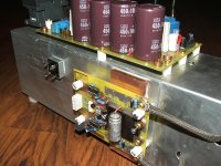
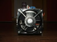
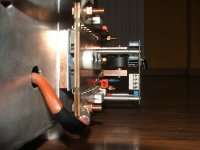
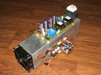
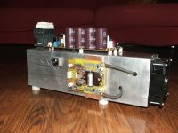
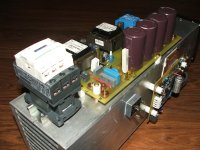
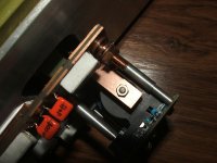
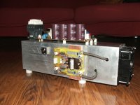
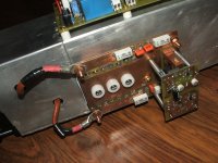
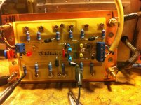
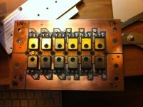
The reason of my registration was mainly to share and ask opinions on this power supply which is not completed yet.
This morning we reached 200A output in DC mode with a 0.1ohm resistive load (immerse in water) and for the moment we've been able to solder in DC with a 70A arc (this is not TIG, standard MMA)
[video=youtube;qqXcv09q4D8]http://www.youtube.com/watch?v=qqXcv09q4D8[/video]
As I said we're still working on the project and there are many things that need to be adjusted so if you don't mind I'll ask for help when I need.
In the meantime, if there is another insane guy like me who is interested in some details for this project please don't hesitate to ask.
Most of the material is in Italian but I can translate and share pieces without any problem.
Max
this is my first post here and first of all I want to thank you for accept my registration.
My name is Max and I write from Milan, Italy.
Together with a friend we are working since almost 2 years to an open source project for a 200A AC/DC TIG welding machine.
For whom is not familiar with the arc welding this machine have to be capable to deliver 200A of current on the welding torch in DC or AC (square wave) with a frequency adjustable from DC to 250Hz.In the TIG mode there will be an arc starter which uses an HF HV (15KV) oscillator in order to generate a low power high voltage arc which will create the path for the high power low voltage welding arc without scratching the electrode as you normally do in a standard welding machine.
We have planned to built many functions which most of them will be software including unbalanced welding current on the two quadrants when in AC: the current of the positive quadrant can be different from the current of the negative quadrant.
All those functions are needed to solder many different types of metal and thicknesses.
Reading some of the posts in this forum I assume that you guys are more related to audio amplifiers so I don't want to bother you with this welding project so much if you're not interested.
The reason of my registration was mainly to share and ask opinions on this power supply which is not completed yet.
This morning we reached 200A output in DC mode with a 0.1ohm resistive load (immerse in water) and for the moment we've been able to solder in DC with a 70A arc (this is not TIG, standard MMA)
[video=youtube;qqXcv09q4D8]http://www.youtube.com/watch?v=qqXcv09q4D8[/video]
As I said we're still working on the project and there are many things that need to be adjusted so if you don't mind I'll ask for help when I need.
In the meantime, if there is another insane guy like me
Most of the material is in Italian but I can translate and share pieces without any problem.
Max

