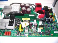
I picked up a blown 2kw sinewave UPS from work the other day, It's 48V input & will run with no mains connected (not at the moment but does run battery only mode).
My interest is for a stand alone inverter.
One of the IGBT's are blown along with a fuse. It appears the likely cause is corrosion on PCB tracks due to the fan cooling & subsequent dust/moisture ingress.
There is a fair amount of small component corrosion for it to be reliable, most likely use parts in another project.
Spending a while analyzing with the following.
DC - DC converter 48V --> 700V center tap (MOSFETS lower left of picture, DS00201 TXF)
Battery charging & auxillary supply is bottom center & right.
DC --> AC inverter is top left with output filtering to the right.
The DC bus is center tap 2.2mf cap bank The midpoint is the Neutral of the AC output.
There is a TMS320 DSP that is doing both the DC-DC converter control & the DC-AC PWM inverter + overall management. The battery charger uses a UC384? control IC.
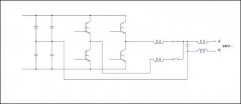
I have a question with the output,
The inverter circuit is duplicated , 2 pairs if IGBT & as can be seen with the 2 output filter inductors(toroids).
One output is thru a N.O. relay contact & the other thru a N.C. relay contact. (quick drawing attached)
Q. I'm wondering if they run just 1 half of PWM inverter to improve efficiency at lower power levels, ?
I might try to get It going just for analysis
!!! Having problems uploading files, Will have to try this afternoon on my home pyoota, sorry...
My interest is for a stand alone inverter.
One of the IGBT's are blown along with a fuse. It appears the likely cause is corrosion on PCB tracks due to the fan cooling & subsequent dust/moisture ingress.
There is a fair amount of small component corrosion for it to be reliable, most likely use parts in another project.
Spending a while analyzing with the following.
DC - DC converter 48V --> 700V center tap (MOSFETS lower left of picture, DS00201 TXF)
Battery charging & auxillary supply is bottom center & right.
DC --> AC inverter is top left with output filtering to the right.
The DC bus is center tap 2.2mf cap bank The midpoint is the Neutral of the AC output.
There is a TMS320 DSP that is doing both the DC-DC converter control & the DC-AC PWM inverter + overall management. The battery charger uses a UC384? control IC.
I have a question with the output,
The inverter circuit is duplicated , 2 pairs if IGBT & as can be seen with the 2 output filter inductors(toroids).
One output is thru a N.O. relay contact & the other thru a N.C. relay contact. (quick drawing attached)
Q. I'm wondering if they run just 1 half of PWM inverter to improve efficiency at lower power levels, ?
I might try to get It going just for analysis
!!! Having problems uploading files, Will have to try this afternoon on my home pyoota, sorry...