MAYDAYDEEJAY
New member
Here comes the story.
Evening every1.
I've decided to show up to all of U DIY freaks one of my projects...
Some time ago I've done some research on the inverter based welding machines as I need one at that time.
I've spend hundreds of hours googling it across Miller, Lincoln, "Chinese High Quality" and some europeans brands.
That results in hundreds of datasheets of diffrent inverter welders and tones of pictures.
In the end I bought for my self an decent IGBT based TIG / MMA inverter to suit my purpose,
and also I've came up with an idea of making a powerfull regulated DC power supply for my garage...
As I own few very powerfull class D car amps, in meaning of supplying them on the bench for testing as well as for other purposes like "jump" starting the cars during the winter and such.
So of my knowledge about the inverter welders, I decided to get myself the simplest one on the market and to have some fun with it...
The first choice was the "MMA200" based on the H bridge with 12 mos's, 3 power trafos 12 dual rectifier diodes and some output chokes...
Obviously i've disassambled it to a piece, drawn the schematic... and at that point, the project died, I had no time at all to get my hands on it for another year or so.
(I will get back to this project when Ill finish the IGBT model)
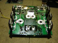
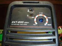
In the mean time I had a chance to get myself another very simple MMA / stick inverter but this one is based on IGBT, and same as with the previous one i took it apart... and guess what ??
...I thought, that the IGBT model, rather expensive, (luckly got this very cheap) will be very well designed etc... bull ****.
Im telling U guys, the "chinese quality controll" does not exist at all judging by the IGBT model.
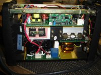
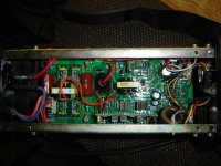
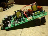
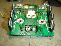
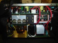
Well lets start from the input to the output...
...Power lead 2x 4mm2 - no earth cable at all.
...no EMI / RFI / input chokes at all.
...input rectifier 35A / 600V way too small as on the input theres no even a small sign of PFC / EMI / RFI.
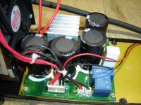
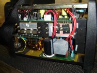
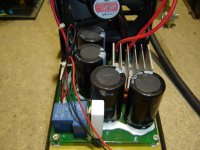
...input buffor 4x 470uF / 450V way too small for the rated output power, current ripple will blow them up in the matter of minutes at full load.
...cables betwen input buffor and the H-bridge stage 2x 0.5mm2 for pos. and 2x 0.5mm2 for neg.
...cables between H-bridge stage and power trafo 2x 0.5mm2 for pos. and 2x 0.5mm2 for neg.
...mentioned cables not soldered at all, for connections are used crapy push-in connectors with contact capabilities of maybe 2A ?? 3A ?? @ max !!
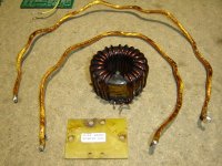
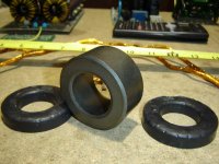
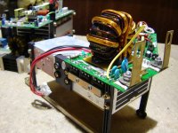
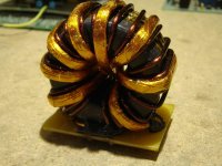
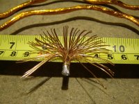
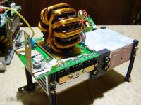
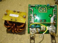
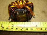
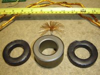
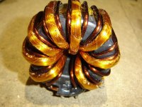
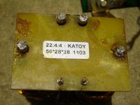
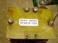
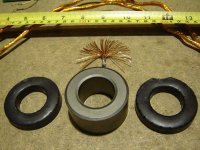
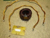
...power trafo T56/32/28 of unknown material - Ferroxcube at similar sizes at 50kHz can do only 1.8 - 2kW...
Does the Chinese have NASA technology for their toroids to throughput 7kW, well let say 5kW through such small core ??
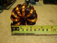
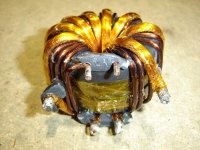
...trafo primary windings made of 3.5mm dia. solid core enamel wire
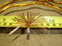
...trafo secondaries (center tapped) suppose 2B 2x 4turns, but the final product happend to have 1x 4turns and 1x 3.5 turns
Well, is it really that difficult to count to 4 ?? Even me, stupid DIY guy can, so why the Chinese engineers can not ??
...trafo primary cross section 9.616mm2 (1x 3.5mm)
...trafo secondary cross section 9.812mm2 (50x 0.5mm) so for 200A output current, its only 20.383A/mm2 WooooooooooW !!
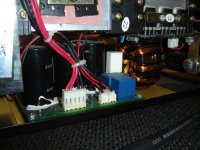
...no output choke at all, how cooooooool is that ??
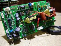
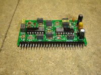
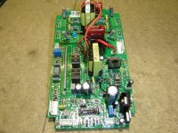
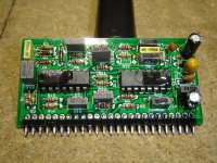
...only") 10 op-amps in the driving circuit of which only two are used, I guess, they tried to ballance the weight of the end product that does not have output choke by noumber of op-amps...
10 op-amps in the driving circuit of which only two are used, I guess, they tried to ballance the weight of the end product that does not have output choke by noumber of op-amps...
...and obviously the maschine uses so highly secret technology and the newest NASA / Military spec IC's that the Chinese boys had to remove IC's and other components names.
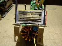
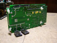
...output diodes... 3pieces for each secondary (current doubler rectifier) each diode rated for 20A cont. (2x 10A) so its only 60A full wave rectifier... for 200A welder, is it enough ??
Components that this inverter uses:
4x GT50J325
6x ESAD92-02R
4x 470uF / 450V
30A / 250V relay / contactor
soft start charging resistor
E25 15:15:15:15:15 IGBT driving trafo + 2x irfz44n and irf9z44n
Anything that not been mentioned is either pointless or I couldn't read the part name.
So at that point !! !! !! WARNING !! !! !! be aware of such inverters, especially if U want to convert it to a DC power supply.
Now what I want:
Rewind the power trafo / replace it, depends of how much space will I get out of this maschine, as the case is very small and its kinda tight inside, but... I have plan but I want to get 400A @ 16V
Add an output choke
Add an output capacitor bank
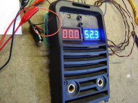
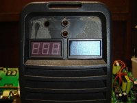
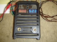
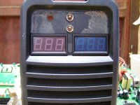
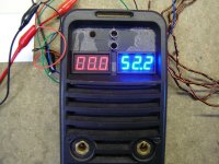
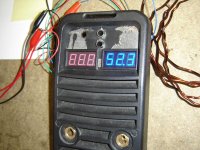
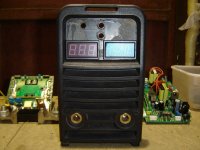
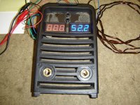
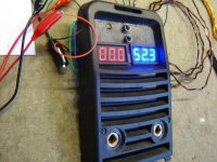
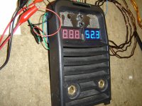
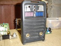
Add output Voltage display - done
Add output current display - done
Add output voltage regulation trim
Add more precise output current regulation trim
Add some EMI / RFI input chokes
Replace driving circuitry with an UC3846
Replace output diodes with 4x DSEI2x121-02A (the cost of these diodes will be equal to the price that I've paid for this inverter) !! !! !!
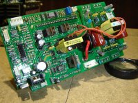
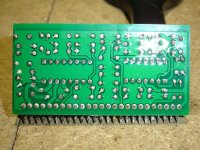
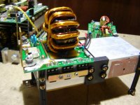
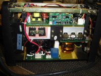
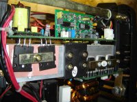
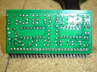
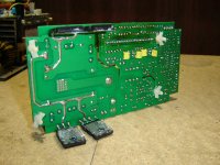
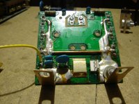
What I've done so far is that the driving "card" is desoldered, and in the bin already, goldpin soldered in its place, and from now on, whenever Ill get some spare time, Ill be working on it as much as I can, to get it working, trying to finish in the proper way what the Chinese engineers started
Basically, it just a matter of proper driver IC circuit, as the welder is already equiped with an +/- 15V independant aux supply, and galvanic isolation betwen the HV and the LV driving circuit.
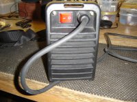
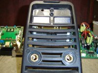
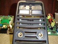
Pictures attached for Your joy ^^
Waiting for Your suggestions
kind regards
mark
and please 4giveme my gramma, as enlish isn't my native language.
Evening every1.
I've decided to show up to all of U DIY freaks one of my projects...
Some time ago I've done some research on the inverter based welding machines as I need one at that time.
I've spend hundreds of hours googling it across Miller, Lincoln, "Chinese High Quality" and some europeans brands.
That results in hundreds of datasheets of diffrent inverter welders and tones of pictures.
In the end I bought for my self an decent IGBT based TIG / MMA inverter to suit my purpose,
and also I've came up with an idea of making a powerfull regulated DC power supply for my garage...
As I own few very powerfull class D car amps, in meaning of supplying them on the bench for testing as well as for other purposes like "jump" starting the cars during the winter and such.
So of my knowledge about the inverter welders, I decided to get myself the simplest one on the market and to have some fun with it...
The first choice was the "MMA200" based on the H bridge with 12 mos's, 3 power trafos 12 dual rectifier diodes and some output chokes...
Obviously i've disassambled it to a piece, drawn the schematic... and at that point, the project died, I had no time at all to get my hands on it for another year or so.
(I will get back to this project when Ill finish the IGBT model)
In the mean time I had a chance to get myself another very simple MMA / stick inverter but this one is based on IGBT, and same as with the previous one i took it apart... and guess what ??
...I thought, that the IGBT model, rather expensive, (luckly got this very cheap) will be very well designed etc... bull ****.
Im telling U guys, the "chinese quality controll" does not exist at all judging by the IGBT model.
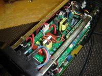
Well lets start from the input to the output...
...Power lead 2x 4mm2 - no earth cable at all.
...no EMI / RFI / input chokes at all.
...input rectifier 35A / 600V way too small as on the input theres no even a small sign of PFC / EMI / RFI.
...input buffor 4x 470uF / 450V way too small for the rated output power, current ripple will blow them up in the matter of minutes at full load.
...cables betwen input buffor and the H-bridge stage 2x 0.5mm2 for pos. and 2x 0.5mm2 for neg.
...cables between H-bridge stage and power trafo 2x 0.5mm2 for pos. and 2x 0.5mm2 for neg.
...mentioned cables not soldered at all, for connections are used crapy push-in connectors with contact capabilities of maybe 2A ?? 3A ?? @ max !!
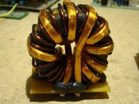
...power trafo T56/32/28 of unknown material - Ferroxcube at similar sizes at 50kHz can do only 1.8 - 2kW...
Does the Chinese have NASA technology for their toroids to throughput 7kW, well let say 5kW through such small core ??
...trafo primary windings made of 3.5mm dia. solid core enamel wire
...trafo secondaries (center tapped) suppose 2B 2x 4turns, but the final product happend to have 1x 4turns and 1x 3.5 turns
Well, is it really that difficult to count to 4 ?? Even me, stupid DIY guy can, so why the Chinese engineers can not ??
...trafo primary cross section 9.616mm2 (1x 3.5mm)
...trafo secondary cross section 9.812mm2 (50x 0.5mm) so for 200A output current, its only 20.383A/mm2 WooooooooooW !!
...no output choke at all, how cooooooool is that ??
...only
10 op-amps in the driving circuit of which only two are used, I guess, they tried to ballance the weight of the end product that does not have output choke by noumber of op-amps......and obviously the maschine uses so highly secret technology and the newest NASA / Military spec IC's that the Chinese boys had to remove IC's and other components names.
...output diodes... 3pieces for each secondary (current doubler rectifier) each diode rated for 20A cont. (2x 10A) so its only 60A full wave rectifier... for 200A welder, is it enough ??
Components that this inverter uses:
4x GT50J325
6x ESAD92-02R
4x 470uF / 450V
30A / 250V relay / contactor
soft start charging resistor
E25 15:15:15:15:15 IGBT driving trafo + 2x irfz44n and irf9z44n
Anything that not been mentioned is either pointless or I couldn't read the part name.
So at that point !! !! !! WARNING !! !! !! be aware of such inverters, especially if U want to convert it to a DC power supply.
Now what I want:
Rewind the power trafo / replace it, depends of how much space will I get out of this maschine, as the case is very small and its kinda tight inside, but... I have plan
but I want to get 400A @ 16VAdd an output choke
Add an output capacitor bank
Add output Voltage display - done
Add output current display - done
Add output voltage regulation trim
Add more precise output current regulation trim
Add some EMI / RFI input chokes
Replace driving circuitry with an UC3846
Replace output diodes with 4x DSEI2x121-02A (the cost of these diodes will be equal to the price that I've paid for this inverter) !! !! !!
What I've done so far is that the driving "card" is desoldered, and in the bin already, goldpin soldered in its place, and from now on, whenever Ill get some spare time, Ill be working on it as much as I can, to get it working, trying to finish in the proper way what the Chinese engineers started
Basically, it just a matter of proper driver IC circuit, as the welder is already equiped with an +/- 15V independant aux supply, and galvanic isolation betwen the HV and the LV driving circuit.
Pictures attached for Your joy ^^
Waiting for Your suggestions
kind regards
mark
and please 4giveme my gramma, as enlish isn't my native language.
Last edited: