Another stab at the ultimate PSU

kubeek

New member
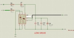
Well, here is the first version of my new SMPS. It is designed to be used in a bass guitar head with a bridged class-d amp.
The reason I chose optocouplers in the gate drive instead of feedback is to allow me to safely measure around the SG3525, and hopefully also a little cheat around compensating the feedback loop, we´ll see about that later.

Things that are still missing:
- another secondary on the main transformer to provide 2x15V for preamps
- yet another high current secondary to generate double HV rails, so that the whole amp can deliver full power for both 4 and 8 ohm loads. This could require changing some connections around shutdown to make the transition between rails smooth.

Feel free to comment :D
 

Attachments

  • 750W smps v.0.3.pdf
    38.3 KB · Views: 221

MicrosiM

Administrator
Staff member
kubeek

I never used 6N137 in that location, I dont know why your are doing so.

That topology is complex in my own opinion, See attached one its tested and robust, even I dont know if any shown that before.

No need to use that driving topology, If you are looking for isolation, use GDT


In all cases that kind of driving is very critical, and lot of things you have to do to in order to make it working properly.

Do you have oscilloscope? necessary tools to do this?

Good Luck!
 

Attachments

  • Driver.jpg
    Driver.jpg
    254.2 KB · Views: 104

kubeek

New member
The problem is that 6N137 has only 50mA of ouput sink current, so I have to use the MC34151 driver which gives +/- 3A and that should be enough. On the other side, the optos and the driver have each delay about 75ns, while a typical fedback opto has about 1-2us.
I don´t want to use GDT because even though I have some from old supplies, I want to make this PSU in larger quantities and can´t wait 4 weeks to get them wound or from some shop that carries them.
I don´t see how you can turn that triac off, but who knows what part it actually is...

Here is the latest schematic and board. I haven´t decided yet whether to put the SG3525 and protection on a separate board, but anyway the basics will be the same.
Other thing is that I haven´t seen line filters in all the other designs, is that some kind of conspiracy to pollute mains with HF noise? :D

I have a 35MHz dual trace scope, an isolation transformer, lots of spare PSU parts and all the other stuff that I will need for this, but thanks for the concern.
The ETD should be coming in about a week or two, so its just about time to make the pcb and start getting components :)
 

Attachments

  • 13-sch.pdf
    42.4 KB · Views: 184
  • 13-brd.pdf
    125.8 KB · Views: 129
Last edited:

MicrosiM

Administrator
Staff member
Gate drive

Thats not triac in that chip. I used that symbol as reference only

its Isolated chip to DRIVE IGBTS. one chip, simple and working and robust! :D

I hope that you will success. And to see your results!
 

kubeek

New member
I can get HCPL3120 in here, but it costs about triple more than the combination I used, I will have to see if the smaller occupied space is worth it.
 

kubeek

New member
The current transformer is anything that you can get and fit to the board. From what I looked into the datasheets, 1:100 or 1:200 CTs can be used safely, but the burden resistor needs to be adjusted according to your model.
 

Malki

New member
hi kubeek
i have 2 qustion
1--what the size of your pcb
2--if i whant to incres the power around 1-1.2kw if it a complex
best tregard
malki shmuel
 
Top