steven
New member

Fichier PDF SMPS 700W.pdf
Lecture et téléchargement du fichier SMPS 700W.pdf sur www.fichier-pdf.fr
") .
.Hi, SilvioI cannot see why the circuit does not work with the IRS chip. They suppose to have the same structure as the dip types. Regarding the led its rather difficult really as during operation the aux winding is supplying the voltage and when the SCR fires it pulls the supply to ground. Adding any resistance here may not ground the supply rail in time. As the chip stop oscillating only the start up circuit is in operation but this will only supply a few milliamps and may not be enough to light up the led.
Regarding some more modifications. Well I hope ZD1 is around 150v. To aid start up you can chainge ZD2 to 12v, ZD3 to 15v and change R8 to 120R. Before making changes check the input voltage before R8, this should be 17v to 20v. Check voltage at pin 1 this should read 13v. With the chip removed the startup voltage at pin 1 should not be less than 10v. I encountered some chips that need 11v at start up and refuse to start at a lower voltage. It could be that fake chips draw more current at start up.
Hi again Benny, the high frequency startup is because the IR2153 does not have a soft start. Charging the secondary capacitors at startup present a nearly dead short especially if having more than 2000uf on each of the center tap windings. However starting the trafo with 3 times the frequency cannot deliver that much current as this is wound for a lower frequency. This will reduce the stress on the mosfets and prevent them from burning.Hi, Silvio
I recently got some more IR"S"2153 again.
I am under the current configuration of IR2153
Some ICs can work, some burn up when they go up, and they are not stable.
I re-read the datasheet of IR"S"2153
It seems that the working frequency is not as high as IR2153(IR"S"2153 is limited up to 100k)
I suspect that the IC may be burnt under 3x frequency startup
*In addition, what are the advantages of 3 times the starting frequency? And why?
Maybe it can be started at normal frequency and it can work well(about 50~70k)
Thanks & Regards
Benny


All seems well. Just one small detail. The primary snubber capacitor usually has a pitch of 7.5- 10mm (ceramic type 1 or 2kv) and the snubber resistor is usually is of the 3watt type. Make sure that these will fit. I cannot determine the pitch used but assuming by proportion. As for the secondary snubber these are usually of a lower wattage but still use a ceramic type.Control board V1.2:
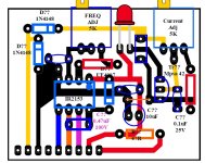
SMPS board V1.3:Fichier PDF SMPS control board V1.2.pdf
Lecture et téléchargement du fichier SMPS control board V1.2.pdf sur www.fichier-pdf.frpdf.lu
Fichier PDF SMPS 700W V1.3.pdf
Lecture et téléchargement du fichier SMPS 700W V1.3.pdf sur www.fichier-pdf.fr
I see no output for a fan motor which normally is essential in an amplifier. This will also help if needing a separate 12-15v dc for the speaker protection relay. Ideally this part does not share a common ground with the preamp stage.Control board V1.2:
SMPS board V1.3:Fichier PDF SMPS control board V1.2.pdf
Lecture et téléchargement du fichier SMPS control board V1.2.pdf sur www.fichier-pdf.fr
Fichier PDF SMPS 700W V1.3.pdf
Lecture et téléchargement du fichier SMPS 700W V1.3.pdf sur www.fichier-pdf.fr
To tell you the truth although I designed the schmitt trigger version I never tried it for real on the smps.
Things you can try
1) You can remove the input thermister and put a 5watt 47R resistor instead. To help a slower start up
2) Following my schematic for schmitt trigger there is a decoupling capacitor which is coming from the sample diodes (1N4148) and has a value of 220nF, You can rise the value slowly 1uF- 4.7uF until you get a start up without tripping on the surge current, Keep to the minimum possible otherwise during a short circuit your fets will not be saved.
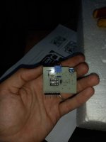
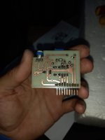
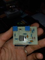
Silvio, how are you? It's been a while, but I've resumed work with this SMPS and now I'm going to use the current limiting module.A picture of a center tapped current transformer. Note the 1.5 turn coupling loop in the bottom.
View attachment 7395
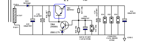
My smps is conditioned according to your smps V2 which has a CT in the primary of the transformer.If you are choosing to use the Current transformer an option for a short circuit protection is available. The pin header however is different from the one using a current limiter and I am afraid to say that you have to make another one. The last version of pin header uses a high frequency start up and also caters for the short circuit protection which uses a small SCR to shut down the supply rail for the IR2153 This is the best option I found as the IR2153 does not have a soft start. The soft start is created by running the smps at around 3 times the frequency. This will not let the trafo expel its maximum power hence limiting the output current. The circuit is designed so that firstly running at the high frequency at startup then resumes to the running frequency after about 1.5 seconds
The current transformer will sense the current in the half bridge and when a threshold is reached fires the scr to pull down the supply to the IR2153.
The current transformer is wound with 0.2mm enameled copper wire and has about 75 turns bifilar wound on a small core about 12 to 15mm dia.
I am posting my final version of this smps which there is some changes in the output capacitors which now contains 6 instead of 4. The schematic is also changed showing the short circuit protection. You can still use your existing main pcb but the pin header has to be changed to cater for the new version. There are also some changes in the values of ZD2 and ZD3 these where done as some chips need a little more voltage at start up otherwise they fail to start if you are not using genuine chips.
There is also the pin header catering for the high frequency soft start and short circuit protection.
In the file you find the description of operation with the short circuit and high frequency soft start.
Regards Silvio
Regarding the pin header I guess the one on the last pdf works best(HF s/start & scr protection) when it comes to protection. It has been tried over and over again and never failed.My smps is conditioned according to your smps V2 which has a CT in the primary of the transformer.
What module do you advise me to put? As for the CT, can I use 0.2mm or higher? Is there any drawback with this? Always respecting 75 double laps.
Is the diameter from 12 to 15mm internal? can iron powder be used?
I thank you in advance for sharing and helping.
The module that has this new file does not have an indicator led to know when the protection is activated.
I edit the latter at 9:00 p.m.:
In V2.11 the improvements that I noticed are the increase of capacitors at the output, the secondary MUR, the Z13V, Z15V and the CT that changed the ratio.
I see that the PCB "HF SOFT START + S/C PROTECTION
WITH SCR" in both V2 and V2.11 is exactly the same, so should I make this PCB for my SMPS?
The CT is 80:1 and not 80:1.5?
My SMPS is made like V2 so the module "HF SOFT START + S/C PROTECTION
WITH SCR" will not be difficult to connect since the pins match well.
Thank you!
I don't know what circuit you are using. Charging secondary capacitors present a dead short for the mosfets at statup. They may blow at times. You can do these adjustments as follows.Hi Silvio & Friends,
I have IR2153 problems again. When starting without secondary capacitors - everything all right. But the problem with the capacitors. Only 330uF is enough to 2153 crash. Sometimes mosfets too. A soft start will probably be necessary.
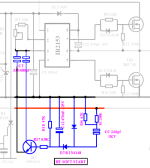
Please, can I use the circuit from the attached picture? Is it verified in practice? The starting frequency is over 200kHz. Can the IC handle it?
Thanks to all for your help.
Is it verified in practice?3) The high frequency soft start will also help in limiting the charge current in the secondary capacitors.
.
Good morning Silvio! I already started to make the PCB of the last PDF. The electrolytic capacitors 1, 47 and 470uF are 25V? Can the others be ceramic or polyester? I will try to get those values.Regarding the pin header I guess the one on the last pdf works best(HF s/start & scr protection) when it comes to protection. It has been tried over and over again and never failed.
The current trafo dia is from the ouside (12-15mm) using thicker wire than suggested (0.16-0.2mm) may not make it possible to fit in the ferrite ring core. 75 or 80 turns will not make a difference in operation. There is adjustment in the preset to set the trip current. Regarding the coupling loop it is mentioned as 1.5 because just passing through the centre will make the coupling rather loose, however passing again from under the ring core gives better coupling. It is still 1 turn around the core.
I hope this helps good luck
Regards Silvio.
That is a 470nf and is not polorisedIs it verified in practice?
Isn't C12 the other way around?

The wrong schematic mark is used. That confused me. I'm sorry........... and is not polorised
Hi Steppler I took a look at the schematic again and C12 is a 470 uF. It is drawn the other way round. This controls the timing of the changeover between high and normal operating frequency.The wrong schematic mark is used. That confused me. I'm sorry.

