EI-33 based half bridge

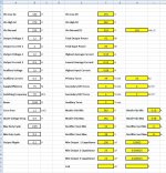
Am starting this new thread after failure to get proper core to build a flyback. The SMPS calculations are as follows:Calculations.JPG
It will be based on a TL494 with totem pole buffers and GDT. An EI-33 core with an AL of 3719 will be used. I had to test 4 harvested SMPS cores to get two with AL>=3000 some EI-33 cores are same sized look same but have very low AL.

System will work with a bias start up and the ic will be powered from an auxiliary supply built on the EI-33 to eliminate mains transformer.

Overcurrent protection will be implemented based on a current sense transformer.

If all above by chance lets hope ends up working i will add TL431 with optocoupler for regulation

Required output is 12V 4A for main use + 12V 500mA for powering logic circuits, relays e.t.c

I will post schematic soon

Any comment is welcome thanks

PS: forget about the CT in the calculations i just left it there in case i would design a dual supply using the same calculation sheet
 

giololucas

New member
Main transformer and GDT wound. In process of winding forward inductor. Giololucas are you in? Lol it reminds me of this song:http://www.youtube.com/watch?v=M90tA302X3k

Are you in.....................

Hehe..

I must warn you I will do it slowly, because I´m very busy at the moment (college :eek:) , but I´m still in, if you are not that hurry.

It will use GDT?
I have to use IR21xx direct drive, small GDTs unavailble for sale in my city and don´t have it in junkbox. ::SD

tks.
 
Hi Giololucas sure i only have some evenings and weekends to spare in too. It will take me some time as well plus i got a PGA3211/PIC pre-amp project i need to move ahead with which is posted here. Do it at your paste and we can exchange info. Effectively i will be using GDT which is already wound i got it out of those CFL lamps:http://www.pavouk.org/hw/lamp/en_index.html take a look at the 4th picture in this link it shows the toroid i have used in my half bridge and which i will use again. Its much cheaper than IR drivers and much safer cause it won't blow your switching ic. If i buy one IR21XX ic in my country i can almost get 8 CFL for that same price. These cores have to be tested of course to find the AL. There are the Philips model which seem good for the job and which i think you can find in any country. I wound mine for an inductance of 1.8 to 2mH. Am sure you'll be using IR2153 :) i got ten of these waiting to be used but its not for now
 
Last edited:

giololucas

New member
Hi Giololucas sure i only have some evenings and weekends to spare in too. It will take me some time as well plus i got a PGA3211/PIC pre-amp project i need to move ahead with which is posted here. Do it at your paste and we can exchange info. Effectively i will be using GDT which is already wound i got it out of those CFL lamps:http://www.pavouk.org/hw/lamp/en_index.html take a look at the 4th picture in this link it shows the toroid i have used in my half bridge and which i will use again. Its much cheaper than IR drivers and much safer cause it won't blow your switching ic. If i buy one IR21XX ic in my country i can almost get 8 CFL for that same price. These cores have to be tested of course to find the AL. There are the Philips model which seem good for the job and which i think you can find in any country. I wound mine for an inductance of 1.8 to 2mH. Am sure you'll be using IR2153 :) i got ten of these waiting to be used but its not for now

Hi zeus.
1 IR = 8x CFL !!!!!! :eek:
In Brazil IR2153 costs 5R$ or 2,5 U$D. But if you don´t keep eyes open, kabooomm!!!!:
How can I measure AL?
Tks
 
I used the formula on this page:http://wiki.4hv.org/index.php/Gate_drive_transformer and i bought an inductance meter like this one:http://www.ebay.com/itm/L-C-Inducta...260?pt=LH_DefaultDomain_0&hash=item3cbbd93db4. or a more sophistiated one depending on your means. But i find this one accurate enough for my needs i think its based on a 16F877 not sure
Principle is simple:
1) Apply known number of turns to a core between 10 to 25 is enough as long as it covers the core completely
2) MEasure the inductance
3) Back calculate AL from inductance
4) Calculate target inductance with AL value calculated in 3)

This does not give you BH curve, saturation with frequency e.t.c but its a good starting point to keep and eliminate cores. Thats how i found the proper GDT core and main core for my half bridge project i posted before. Like i said not all EI-33 have high AL some have very low AL values. Same for thoise CFL toroids that i use as GDT cores i took apart some burnt out lamps and started measuring until i foudn a decent Toiroid. once you find the make and model just stock them for future projects.

Regarding IR ic's i had to buy them off ebay. The price difference is very huge compared to local ones but you need to watch out as well. There are many counterfeit IR ic's around. You are very lucky if you can find them at affordable prices and they work properly if well configured
 
Last edited:
Regarding progress am currently starting to build the power section on a modified stripboard to leave only the copper i need and solder connections later they are out of project board here and i have ordered some on ebay am waiting for them to arrive. I have no choice but this in mean time
 

giololucas

New member
I used the formula on this page:http://wiki.4hv.org/index.php/Gate_drive_transformer and i bought an inductance meter like this one:http://www.ebay.com/itm/L-C-Inducta...260?pt=LH_DefaultDomain_0&hash=item3cbbd93db4. or a more sophistiated one depending on your means. But i find this one accurate enough for my needs i think its based on a 16F877 not sure
Principle is simple:
1) Apply known number of turns to a core between 10 to 25 is enough as long as it covers the core completely
2) MEasure the inductance
3) Back calculate AL from inductance
4) Calculate target inductance with AL value calculated in 3)

This does not give you BH curve, saturation with frequency e.t.c but its a good starting point to keep and eliminate cores. Thats how i found the proper GDT core and main core for my half bridge project i posted before. Like i said not all EI-33 have high AL some have very low AL values. Same for thoise CFL toroids that i use as GDT cores i took apart some burnt out lamps and started measuring until i foudn a decent Toiroid. once you find the make and model just stock them for future projects.

Regarding IR ic's i had to buy them off ebay. The price difference is very huge compared to local ones but you need to watch out as well. There are many counterfeit IR ic's around. You are very lucky if you can find them at affordable prices and they work properly if well configured

Thank You Zeus.
I´m used to measure inductance with a homebrew sinewave generator (wien bridge) and oscilloscope by lissajous figure, since I don´t have LC meter.
About the IRs they look original ones, and it´s working well until now... (let´s see it in 2nd prototype).
I worked this weekend in my 2nd SMPS , pcb is ready and just soldered some parts... it´s a long way ahead.
I will open a new thread when I finish it to post final tests and schematics.
 

MicrosiM

Administrator
Staff member
very interesting project, I am always looking to get rid of those transformers as the AUX supply, and to be able to replace them with small and tiny one!
 
Hi Microsim thanks for teh reply my aim actually is to power the SMPS ic from the main core itself which is why i have a 15V output from my main core. for the smps to start the ic needs to be provided with power until it turns on fully.
From what i know the following is possible:
1) Bootstrap start up: It the simplest to go and uses a res+ cap to the ic supply just to power it up with a few hundreds of milliamps of current. When the mosfet start swithing the supply from the main SMPS transformer supplies the IC to keeep it working but the res+ cap keep working.

2) Switch off discrete high voltage regulator: Like in Marty Brown 280W half bridge SMPS which i will be using. The regulator supplies the IC for statup but when the SMPS starts working the voltage provided to the ic switches off the regulator. There are also specialized ic for this purpose but they are made for UC38XX series.

3) Capacitive or resistive mains supply it uses capacitive reactance or resistance to drop mains voltage and power completely the IC. It needs to be calculated properly but caps/resistor get large and it is not isolated from mains. Good thing is no additional turn is needed on main transformer but for 4-10 turns less its not a big deal.

4) Additional SMPS (e.g. ST Viper series) that completly power the ic in other words a SMPS powering another SMPS but at this point you add double complexity and reduce reliability by even more given that if the auxiliary smps fails you have more to check and its more complex to build.

I will be going for soln 2) above but i will implement and test it when the smps is properly working in the time being the ic will be powered from a regulated supply. I will post the schematic soon am still toucing values here and there inside but its completely based on my previous half bridge design
 
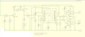
Oscilaltor Schematic

Hi am pretty busy at the time being but this is the oscillator schematicOscillator.JPG. I will post power schematic soon
 
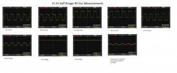
Prototype built and passed 40Vac test

The protoype is built and i've just captured the waveforms at 40Vac. I wanted to upload them here with a pic of the protoype but am unable to anyways. I'll keep posted about the progress.

Am currently adding current sense protection before testing at 110Vac
 
Passed 130Vac Test

Here are the 40Vac waveforms: Ei-33-4-Vac.jpg the prototype passed the 130Vac test with one 100W bulb in series.

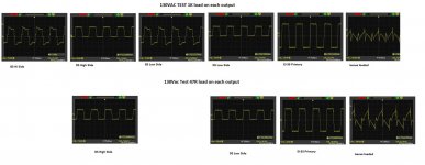
Output voltage +-8.2V with 1K on each output and +-7.3V on each output with 47 ohm load.

I'll go ahead and measure the waveforms at 130Vac and try upload it here
 
130Vac measurements light and medium loading

130Vac measurements light and medium loading:EI-33 130Vac test.jpg

Am a little bit concerned about what the Isense is showing !!!:
 

MicrosiM

Administrator
Staff member
try to play with your series cap, or add 2uh coil in series with your transformer primary.

lets try that first
 
Top