Hello everybody!
Let me first introduce myself. I am an electrical engineering student, working on SMPS.
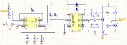
In attached pictures you can see my schematic. I am using PWM driver TL494 for generation of 50 kHz/40% duty cycle signal that is going further on full bridge driver IRS2330. IRS2330 is driving four MOS transistors IRFP450. Those transistors are connected to primary of ETD49 core and power supply for primary is controlled and rectified by variac (Vdc). On the secondary I have charge pump that is generating high voltage. I measure high voltage with resistor divider and regulate it with schmitt trigger. That means when voltage reach recommended value, the output of schmitt trigger goes from 0 to 12V. Output of schmitt trigger is connected to pin 3 of TL494, so it turns out driving of FETs and voltage is being regulated that way.
Everything (regulation & signal shapes) works fine as far as the voltage on transistors (Vdc) is below 150V. When I start lifting the voltage from 30V up, the voltage on floating channel of IRS2330, that is voltage between Vb1 and Vs1, starts falling down, and when I reach cca 150V the IRS2330 is destroyed (floating channel only).
Does anybody know what is the reason that voltage on floating channel is falling down with rising the Vdc voltage? Or what could possibly be the reason for destroying the IRS2330?
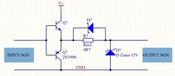
I tried to put the push-pull circuit between IRS2330 and gates of transistors but it didn't improve the circuit.
If anybody have suggestions or similar experience, please feel free to write them.
Marko
Let me first introduce myself. I am an electrical engineering student, working on SMPS.
In attached pictures you can see my schematic. I am using PWM driver TL494 for generation of 50 kHz/40% duty cycle signal that is going further on full bridge driver IRS2330. IRS2330 is driving four MOS transistors IRFP450. Those transistors are connected to primary of ETD49 core and power supply for primary is controlled and rectified by variac (Vdc). On the secondary I have charge pump that is generating high voltage. I measure high voltage with resistor divider and regulate it with schmitt trigger. That means when voltage reach recommended value, the output of schmitt trigger goes from 0 to 12V. Output of schmitt trigger is connected to pin 3 of TL494, so it turns out driving of FETs and voltage is being regulated that way.
Everything (regulation & signal shapes) works fine as far as the voltage on transistors (Vdc) is below 150V. When I start lifting the voltage from 30V up, the voltage on floating channel of IRS2330, that is voltage between Vb1 and Vs1, starts falling down, and when I reach cca 150V the IRS2330 is destroyed (floating channel only).
Does anybody know what is the reason that voltage on floating channel is falling down with rising the Vdc voltage? Or what could possibly be the reason for destroying the IRS2330?
I tried to put the push-pull circuit between IRS2330 and gates of transistors but it didn't improve the circuit.
If anybody have suggestions or similar experience, please feel free to write them.
Marko
Attachments
-
 Untitled-1.jpg308.5 KB · Views: 509
 -
 Untitled-2.jpg155.1 KB · Views: 220