Gate Drive Transformer Issues

twenglish1

New member
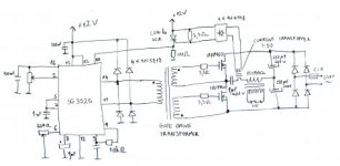
So got my SG3525 driver circuit completed and checked the output with my scope, i am getting two opposite phase square waves, 20khz each, 50% duty cycle. I tried many times to create a gate drive transformer and none were outputting the correct waveform, i have tried multiple "salvaged" toroids and a few E cores, tried different numbers of turns and all with the same result:

Here is the output of the SG3525:

The voltages are the same just offset a little


Failed Transformer attempts:


and:


the two failed attemtps were two different toroids, i recevied the same resultes from the e cores i tried, what is my problem? i am using more than enough turns to prevent saturation, also the gate drive transformer attempts only have one primary and one secondary in a 1:1 ratio
 
Last edited:

MicrosiM

Administrator
Staff member
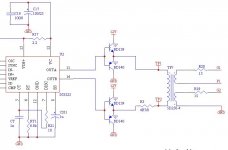
Are you connecting the GDT directly to the SG3525?

Are you using any drive circuit to drive the GDT?

Show me the cores you are using.

Waves are very bad from the GDT for some reason.

Regarding turns, you need around 13 on primary, same on secondaries, this will make you run quick without problems, other issues I can expect is BAD core, or Bad drive


Regards
 

twenglish1

New member
The GDT is directly connected to the sg3525, maybe i should try adding two transistor pairs as a buffer to take some of the load off the sg3525? that was my original plan but i have seen people driving the GDT directly driven by the sg3525 before. here are two pictures of the cores i have tried, all were salvaged from PC or TV switchmode powersupplies:


and a close up of the E core i tried:


All toroids i had the primary and secondary tightly twisted together before wound around the cores, with the e core one is ontop of the other with a layer of electrical tape between them

As mentioned i recieved either one of the two bad waveforms in the orignal post from each one
 
Last edited:

MicrosiM

Administrator
Staff member
First mistake is clear, connecting the transformer directly to the SG3525 is wrong, at least you should connect it via 200nF capacitor and 10R resistor.

I advice you to use 4 transistors to drive the GDT.

I am sure that at least one core from the ones shown will work once you fix the GDT drive circuit

Regards
 

Peeter1682

New member
I probably had the same issue while I was trying to make half-bridge with TL494. I used little EE core from ATX PSU, think it's called base drive transformer. I winded 4x 15 turns, 2x primary (push-pull drived directly from TL494, also used anti-parallel diodes for output transistors) and 2x secondary. When I turn on auxiliary supply circuit drain a lot of current and output waveform's look very similary to your's. So I tried another core - FT82-43 which worked. So I also tried to use full bridge driver (4transistors) for EE core and it started to wok. So IMHO, there is a issue during starting up a circuit. During this time output transistros may not switching with defined duty cycle and core get's into saturation before circuit stabilise. You may try to cut the VCC from your GDT then start circuite and connect it back. IMHO it should work.

Or manually put error amplifier into high state for a few seconds after startup circuite.
 
Last edited:

twenglish1

New member
My sg3525 is configured for a slow softstart, you can actually watch the voltage rise on the scope in real time, and in a lot of the testing i have been doing I was connecting the GDT after the circuit was started. I tested what microsim mentioned about using the resistor and capacitor, I was unsure how he suggested to hook it up, so I put a resistor and capacitor of the values mentioned in series with each output of the sg3525, it seemed to help a little but I did not get a chance to try hooking the resistor and capacitor in parallel as an rc filter and then putting that in series with the GDT, that will be my next test. If you are having problems with start up, I read somewhere that placing a 10k resistor between the gate/base and the source/emitter of the transistor or mosfet will prevent the base/gate from floating during start up or receiving interference that may cause unwanted turn ons
 

twenglish1

New member
Did I have it right about the resistor and capacitor in series with each other and that in series with the GDT? Should I have a resistor and capacitor on both outputs of the sg3525? And does it matter if the capacitor or resistor is first in the series?
 

twenglish1

New member
That was my original plan, I just figured I would try it without the two transistor pairs first because I have seen it done without them, the sg3525 also has the same two transistor pairs on the output stage inside the sg3525
 

twenglish1

New member
I have noticed from trying the above circuit with the diodes before the GDT that more heat is generated from the sg3525, even when the transformer isn't connected, I also didn't notice any difference in the output waveform of the GDT when using the four diodes
 

MicrosiM

Administrator
Staff member
I have noticed from trying the above circuit with the diodes before the GDT that more heat is generated from the sg3525, even when the transformer isn't connected, I also didn't notice any difference in the output waveform of the GDT when using the four diodes


Did you check waves of your SG3525? without GDT connected? make sure its working, and you have clean waves.

Before you connect the drive circuit, and before you connect your GDT.

I think that the SG3525 is damaged by now!
 

twenglish1

New member
Yeah I frequently check the output of the sg3525 it hasn't changed since I posted the picture of the scope image, could my power supply not be supplying enough current?, roughly how much current should a toroidal GDT like I am building require?
 
Top