Gate Drive Transformer Issues

Jagd.Panther

New member
I'm going to use insulation tape between each winding, that's why I buying bigger cores. Is that sufficient? I do have many 50hz transformers and I'm see no reason to buy additional copper.
It will work

However the best approach is not getting bigger cores to fit more wire, but choosing core with higher perm so you can use less wire. One of the best winding method to get minimal Ls is to wind GDT bi-/tri-/multi-fillar.

What is your target switching frequency? Do you need cycle-by-cycle cycle current limiting?
 

lynxlynx

A rumbling soft motor
Meanwhile while my cores are shipping I made this circuit to test the cores with arbitrary duty cycles and frequencies from 5kHz to 100kHz (but can be of arbitrary frequency that is supported by TL494). Minimum parts required.

Hope this helps someone.
 

Attachments

  • 494_gen.jpg
    494_gen.jpg
    36.1 KB · Views: 26
  • 494_gen.zip
    38.2 KB · Views: 60

lynxlynx

A rumbling soft motor
The circuit was changed since I posted it, it also featured NOT logic at outputs so it is UNABLE to drive e.g. IR2110 things. Beware!
The attached I believe a normal design and it also drives IR2110 test full bridge properly.
I also needed to place a 103 cap between DTC and ground to eliminate all noise.

Also what are you going to drive with thing thing?

It is a test circuit. For long time I needed simple square wave generator.

I am going now to play a lot with my new GDTs (see next post) that just arrived. Because circuit can give me almost arbitrary frequency within ferrite range and almost arbitrary duty cycles up to 45% (datasheet value) I can see waveforms with my tube :) and current consumed by core and from these values I can adjust number of turns properly and never disturbing my main circuit board. Then after adjusting I will place the prepared GDT into board and see do my calculations right or not.

Looks like you forgot to add decoupling caps

I will experiment with multiple modes so it is intended that there is only HF AC square signal output.
 

Attachments

  • 494_gen.jpg
    494_gen.jpg
    52.7 KB · Views: 17
  • 494_gen.zip
    65.3 KB · Views: 33
Last edited:

lynxlynx

A rumbling soft motor
And these are shipped cores, 4 of each. There are only three of them because these are all suitable small cores which were available for order. Maybe I will order cores from aliexpress in future.
I tested now only small N87 epoxy coated and middle Russian one and they repeat signal very well except that I need 2-4 turns more for middle. The biggest is too large IMO but still better safe than sorry and order again. The small is going to be used only in half bridges (or, at least I will try to wind it with magnetic wire and insulate), while middle is the best choice IMO just need to adjust number of turns properly. I think middle can be made with normal insulated wire. Will see.
 

Attachments

  • 8519.jpg
    8519.jpg
    80.5 KB · Views: 18

lynxlynx

A rumbling soft motor
And these are shipped cores, 4 of each. There are only three of them because these are all suitable small cores which were available for order. Maybe I will order cores from aliexpress in future.
I tested now only small N87 epoxy coated and middle Russian one and they repeat signal very well except that I need 2-4 turns more for middle. The biggest is too large IMO but still better safe than sorry and order again. The small is going to be used only in half bridges (or, at least I will try to wind it with magnetic wire and insulate), while middle is the best choice IMO just need to adjust number of turns properly. I think middle can be made with normal insulated wire. Will see.

So far so good, the GDT question I hope is resolved. I used the biggest one from photo and instead of having nice time with insulating each winding I just found an old computer flat cable, tested it's insulation with 1kV coil and just used 4 threads from it. 9 turns were enough. For primary I used thick magnetic wire.

You Jagd.Panther were right, I am having nice "noise" issue unresolved. Again. I had it almost always with these types of circuits before, but always I fail to remember how to resolve it.

Driving GDT from separate circuit I posted is nice and clean: nothing heats up, the duty cycle is regulated freely, and on 20-30% cycle I see shining bright 36V 60W bulb. But when main circuit comes into play well... only noise and crackle sounds from main transformer, load flickers. On SG3525 pin 1 I see noise. So I am going to investigate more. Still do not believe that there is layout issue, I had exact same with previous "big" circuit and I resolved that, somehow. Maybe I just need bigger caps somewhere.
 
Last edited:

Jagd.Panther

New member
Try to start SMPS w/o voltage feedback. Just feed the error amp with a potentiometer hooked up to a Vref and gnd (disconnect comp network form comp pin, connect comp pin to err amp inv input), add a 0.1...1u ceramic cap to error amp input and gnd (place it very close to the 3525)
 

MicrosiM

Administrator
Staff member
Today built a new GDT for a new testing and experiments, hope below pictures will help you somehow.

DS253 is the signal directly from the output of the GDT.

DS252 is at the G of Mosfet (Included a transistor).

I have perfect driving using this configuration, also this core is too big, the final one is smaller. just used it for testings
 

Attachments

  • DS0252.jpg
    DS0252.jpg
    42.9 KB · Views: 45
  • WP_20150929_20_41_24_Pro.jpg
    WP_20150929_20_41_24_Pro.jpg
    1.5 MB · Views: 53
  • DS0253.jpg
    DS0253.jpg
    42.3 KB · Views: 38
Last edited:

lynxlynx

A rumbling soft motor
Today built a new GDT for a new testing and experiments, hope below pictures will help you somehow.

DS253 is the signal directly from the output of the GDT.

DS252 is at the G of Mosfet (Included a transistor).

I have perfect driving using this configuration, also this core is too big, the final one is smaller. just used it for testings

Very nice forms, mine do probably same (and scope is bad). Can you show how it performs under different lesser duty cycles?
 

lynxlynx

A rumbling soft motor
I have many ATX transformers to disassemble and you MicrosiM remind me that I can wind transformer with magnetic wires with proper insulation. Is insulation on ATX chinese wires is enough? Had someone reused it with success?

Just took one and tested. Well, it fizzes under 1kV but sustained the voltage. But still unsure, especially after thermal influence (300C) needed for disassemble.
 

Attachments

  • 9278.jpg
    9278.jpg
    88.6 KB · Views: 39

MicrosiM

Administrator
Staff member
I have many ATX transformers to disassemble and you MicrosiM remind me that I can wind transformer with magnetic wires with proper insulation. Is insulation on ATX chinese wires is enough? Had someone reused it with success?

Just took one and tested. Well, it fizzes under 1kV but sustained the voltage. But still unsure, especially after thermal influence (300C) needed for disassemble.

I never used those wires from ATX power supply, but you can use them as long as there is NO scratches in the outer insulation.
 

Jagd.Panther

New member
I have negative experience with silpad from ATX PSU: I used silpads from secondary TO274 schottky's in 600v halfbridge running at ~95khz. Lost two 900v mosfets, few resistors, diodes, PTC, fuse when silpad isolation failed after ca 5 minutes idling.
 

lynxlynx

A rumbling soft motor
I have negative experience with silpad from ATX PSU: I used silpads from secondary TO274 schottky's in 600v halfbridge running at ~95khz. Lost two 900v mosfets, few resistors, diodes, PTC, fuse when silpad isolation failed after ca 5 minutes idling.

Got it. Thanks.

Try to start SMPS w/o voltage feedback. Just feed the error amp with a potentiometer hooked up to a Vref and gnd (disconnect comp network form comp pin, connect comp pin to err amp inv input), add a 0.1...1u ceramic cap to error amp input and gnd (place it very close to the 3525)

Tested it today.

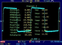
Without ANY feedback the SMPS goes full voltage the transformer can provide and load shines (of course). There is no any noise in this mode. As in manual mode with external circuit that drives GDT.
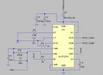
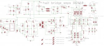
As for potentiometer I did not understand fully. I rebuilt circuit as shown on image, but:
- Below 0,7V between NI and GND the IC just shutdowns.
- Between 0,7 and 3,3V it just works full duty cycle.
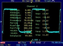
- Above 3,3V I hear very similar hiss and crackle from transformer.

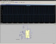
That's strange, I checked circuit, that's against simulation did show.

My control originally looks like that I attached.
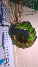
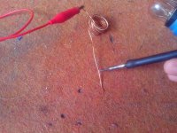
 

Attachments

  • 6516.jpg
    6516.jpg
    218.2 KB · Views: 24
  • control.jpg
    control.jpg
    63.3 KB · Views: 52

Jagd.Panther

New member
OK, before going to feedback you must have SMPS stable in open loop mode.

Try to add a cer.cap of ~0.1uf from non-inverting error amp input to ground. Connect Sync input to ground.
 

lynxlynx

A rumbling soft motor
Still random flickering and sound, no change. But I managed to accidentally connect cap between Vref and gnd and noise almost gone away. But still some fraction (very low volume) can be heard, and mosfets do not want to stay cool (versus almost cool operation in open loop mode). Did not checked it with scope yet.
 

lynxlynx

A rumbling soft motor
After days of simulating control and feedback in LTSpice then trying it real on board I realized that I was on wrong way. I remembered about snubbers all across the GDT (before bjt driver and after) and just added another 47R-10n RC across GDT primary and suddenly - no hiss, no noise, all goes well except still strange hum from transformer and fets still heat some bit. I hope it's due to low aux supply (I really need to redo it from it's current 11,6VDC to at least 15VDC) and poor made GDT.

Maybe snubber requirement is because of noise walks on the board, or GDT made quick but I really happy it's up and running again.

This magnetics stuff really hard to get at once, and my next SMPS is going probably to be with IR2110 with flyback common ground. But development continues and I happy to know more learning from my own mistakes.
 
Last edited:

stewin

Member
hi all i have been using this non regulated smps,
it uses a transfomer gate drive circuit , without any issue with irfp460 also with irf740 (gdt is ee16 1:1 i have used 12turns 16turns even 22turns all work well) .

i tried using igbts . the igbts heated on testing so i never used them . my schematic is below with photos of it working.
 

Attachments

  • gtG smps lp small components clear.pdf
    41 KB · Views: 116
  • gtG smps lp small schematic.pdf
    63.6 KB · Views: 123
  • gtG smps lp small bottom.jpg
    gtG smps lp small bottom.jpg
    234.4 KB · Views: 74
  • gtG smps lp small.jpg
    gtG smps lp small.jpg
    290.5 KB · Views: 65
  • IMG_20150817_205206_1-Optimized.jpg
    IMG_20150817_205206_1-Optimized.jpg
    43.8 KB · Views: 69
  • IMG_20150817_205217_1-Optimized.jpg
    IMG_20150817_205217_1-Optimized.jpg
    39.6 KB · Views: 53
  • IMG_20150828_114530-Optimized-1.jpg
    IMG_20150828_114530-Optimized-1.jpg
    89.3 KB · Views: 51
  • IMG_20150828_114536-Optimized.jpg
    IMG_20150828_114536-Optimized.jpg
    90.7 KB · Views: 46
  • IMG_20150828_114112-Optimized-1.jpg
    IMG_20150828_114112-Optimized-1.jpg
    133.8 KB · Views: 46
  • IMG_20150828_114157-Optimized-1.jpg
    IMG_20150828_114157-Optimized-1.jpg
    124 KB · Views: 50
  • gtG smps lp small schematic.jpg
    gtG smps lp small schematic.jpg
    263.5 KB · Views: 116

stewin

Member
just found this at a forum in edaboard . i wonder if it will drive the igbt or it is a better way to use gdt method

edaboard.com switch mode arc inverter welder schematic pg 4 smps gdt smooth 4834.gifedaboard.com switch mode arc inverter welder schematic pg 4 smps gdt smooth 4834.jpg
 
Top