Isolation transformer

Silvio

Well-known member
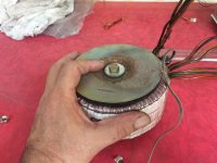
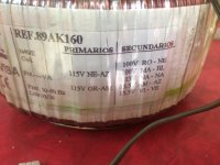
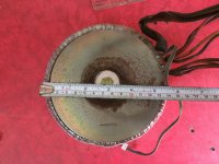
Hello everyone I need a soft start for my new isolating transformer. This is to power the whole bench when working on mains etc. The capacity is around at least 2.5Kw at 200volts output. This transformer used to power an amplifier of 6kw and it had two of these. Does anyone have a schematic so I can make one?

IMG_0280.JPGIMG_0278.JPGIMG_0277.JPG
 
Last edited:

fourtytwo

Leaving bad site ASAP!
Hi Silvio, nice transformer, how many va ? Does it actually trip your breaker ?
Myself I use a 500W EI core isolater in combination with a variac just for the smps I am working on, not the whole bench :)
John
 

Silvio

Well-known member
Hi John it is only occasionally that it use to trip the breaker just when I used to switch it on load when I forget to remove it prior to switch on. You can take a look at the whole set up as from then on I enclosed it in an old ups box and added some turns to the secondary windings to get it up to 220v here is a post regarding enclosure of the trafo on post #7 http://www.diysmps.com/forums/showthread.php?872-1000w-smps-based-on-LUDO3232 and the simple soft start I constructed for it on this post. http://www.diysmps.com/forums/entry.php?139-Simple-soft-start-for-high-power-transformer
Well its powering the whole bench now and while doing tests I don't have problems of being electrocuted and neither burning my scope.

Regards,

Silvio
 

fourtytwo

Leaving bad site ASAP!
Hi Silvio, I am sorry I was late to the thread, I didnt realize you had already solved your problem, nice work :) Nice 1Kw psu too but am a bit foxed by the control chip but I understand this is a proven design so if it works go with it :) My problem here in the UK is sourcing Litz wire at a reasonable price :(
 

Silvio

Well-known member
Hi John, I don't even find to buy Litz wire here. I made some reserch and learned some techniques how to group and re-group in making Litz wire. I bought a reel of 0.16mm ECW and I make my own. I use a hand drill so I can count the number of twists in each group this way I can be quite accurate and can produce similar wire groups with endless combinations.
It doesn't take much tough you need some space to work and some common sense. I attach a piece of wood to my workbench away from the vice according to the length needed plus a few inches more than needed. I attach a wire hook to the drill chuck and tie the drill in the vice. I tread the wire (EX 5 times) between the piece of wood (this has a nail on top to tie the wire to) and the hook in the drill chuck. Then I take the drill out of the vice and start spinning and counting the amount of spins until I get a wire with say 5-7 twists per inch depending on the number of strands. I take note say I tuned the drill hand wheel 30 times for example. I cut the wire out of the nail and hook and start the next group. Finally I re-group the the groups together according to the number of strands needed. Groups can be 3, 5, 7, 9 etc depending on the wire diameter. I do not group more than 7 at a time as the wire I use (0.16mm) does not lend itself very good if bunched more than 7. I also keep in mind that every strand has to be exposed on the outer edge of the bunch when twisted. I then re-group with an odd number of bunches say 3,5,7 etc. You tell me why its always odd numbers? Well try to untie a small piece of rope or tread and you always find odd numbers. In odd numbers grouping comes symmetrical and evenly wound. I done quite a few number of litz wire and it came out good. Well you get experience as you go along and get used to the tension needed and so on. Disadvantages in Litz wire is that due to every strand has its own insulation, the final diameter of the wire will come larger compared to solid copper for the same cross sectional area. The other disadvantage is that you have to bare every strand at the end of each wire for soldering etc. and if it happens that the type of varnish does not come off with a hot soldering iron you have to prepare yourself for some patience like me to burn the edges with a lighter and scrape off the residue patiently with steel wool :)

I hope you find this helpful

One other thing regarding the chip used in my 1000 watt smps I think you noticed that I made the pwm board detectable so that If I want to use another chip I can do so freely just by changing only that and not have to re-design the whole pcb. If you have a suggestion to make feel free to say it. I would be happy if you got a working schematic that I could try.

Regards

Silvio
 

fourtytwo

Leaving bad site ASAP!
Hi Silvio, Wowwww amazing!!!! you are so dedicated! I have made litz in 0.4mm for example just 7 strands but not real rope like you are making that's simply amazing to me. Even with 7 strands I find it difficult to start with an even tension in all the wires. I cheat and use an electric drill with a bent nail in the chuck, same other end in a vice and I check the turns/inch by eye, all very amateurish so seriously limits my high frequency work consequentially I stay below 25Khz for high power stuff. Litz is available on Ebay but only at silly prices, likewise specialist suppliers but they want to sell you a kilo at a time! Anyway guess i am reducing my switching losses, I don't mind using bigger cores but the bigger ripple capacitors get to be a nuisance sometimes.

On the control chip front it's interesting about this current mode center tap drift, I have not had a problem BUT my smps's don't have voltage regulation (using feedback) so that's one difference. I use current mode controllers because of the inherent controlled start characteristic, fast response to a current event (robust mosfet protection) but most importantly not resetting the steering flipflop on a current event so during start up or indeed a short circuit/overload alternate switching continues allowing everything to work normally all be it at a smaller duty cycle. Overall this also gives me a constant power overload characteristic which is very beneficial in my application.

I am sorry to hijack this thread but another interesting question is how you deal with creepage and clearance in the transformer ? For me I use TIW (Triple Insulated Wire) for the grid side winding, again this is even harder to Litz and guarantee no damage to the critical insulation IMOP.

Regards

John
 

Silvio

Well-known member
Hi John, regarding the creepedge voltage I use 3 layers of Mylar tape between the grid winding and secondary taking care that at the edges I leave enough tape with the first layer so that when the layer/s are finished I overlap the tape remaining on the side over it with the goo facing upward this time and enclose the winding in a further one or two layers or so. That is my triple insulation.

It is rather difficult to leave mandatory space at the ends especially when calculating and trying to fit in a single layer not trying to overlap windings thus keeping tight coupling as much as possible between them. I believe that a layer or two of tape is far lower in height than winding wire.

Nearly every time you wind a core and having a bit of high voltage involved you try to squeeze as much as possible in it and not compromising copper losses due to wire thickness.

Have you ever tried using Excellent IT software in your calculations? I have some issues I do not fully understand maybe you
could guide me in.

About the fact of the center tap voltage wonder i experienced that a little and my 1000 watter does a bit on light load say 100 watts or so (0.8volts) but stabilizes on heavier loads.

One other question I'd like to ask is in a normal hard switched smps how would you know that it is resonant. Is it the wave shape it produces on the scope (trapezoid rather than squarish) I read on this forum that people here using this quote. I have the small smps (my first build) produces a trapezoid wave and stays that way with load or no load. it only changes from the top on heavy load slanting a bit. Probe (X10) attached directly across the primary winding. Isolated scope and isolated supply from different sources.

regards,

Silvio


IMG_0443[1].JPG IMG_0441[1].JPG

No load full load 450 watts
 
Last edited:

fourtytwo

Leaving bad site ASAP!
Hi Silvio, I always get timed out when writing replies here it seems rather short or maybe I am just slow :)
I noticed in transformer construction people use 2 or 3mm wide end spacers to force the windings not to use the whole width and then use mylar, this is about the only way to get the CE required distance but I like your idea of wrapping the entire winding as a parcel though I have not seen it done like that on commercial trafo's, maybe once again it would not guarantee sufficient creepage path length. Also its a real pain if your trying to sandwich multiple layer primary and secondaries, I think that is why I embraced TIW with relief once I discovered it :)

Yes I use the excellent IT software and should make a contribution :) As you say it's a bit difficult to understand at times, fortunately I have long done my own trafo calcs too so I know when the answer is way out, it doesnt seem to work for rings at all and its inductor calculator has to many parameters! The basic transformer stuff is ok for ETD cores at least, is there any particular bit of it thats causing you a headache ?

In the case of hard switching I see leakage inductance as an arch enemy so always try to completely minimize it consequentially I don't think I have ever seen anything approaching resonance. My current waveforms look like the classic ramp and voltage waveforms the classic square. If you dont have that possible your coupling cap us to small (rounded tops to current waveform on heavy load) or output inductance to small (squarish current waveform).

I was going to post some waveforms but just found I corrupted the folder way back when! Yours at first glance look strange (apparently very slow rise n fall) but I think this is your deadtime in conjunction with VERY heavy snubbing! If you have a current transformer in the primary its far better to look at current waveforms if you can.

I have been cutting steel today to add a fan in situ outdoors up a ladder in 0C on a 1kW single phase boost converter who's heat is getting out of hand hahaha

Regards
John
 

Silvio

Well-known member
Hi John, I did not fully understand what exactly you mean by triple insulation, do you sleeve your grid winding wire? or you buy cotton wound Litz or something similar? or is your ecw triple varnished?

Regarding Excellent IT software I made a post a few months ago when I started gathering information before my 1000 watt smps.
http://www.diysmps.com/forums/showthread.php?864-Help-needed-understanding-Excellent-IT-software
in this post I asked some questions regarding maximum flux to be used. I know that the higher the input voltage the higher becomes the flux density for a given number of turns. I asked also about the dead time, and core saturation. One last question I like to add is regarding diode voltage drop. Is it for one diode? If you have a bridge on the output do you have to double this?

About the wave form on the small smps 350w I taught it was a perfect wave form. As far as snubber used I am using a 220pf in series with a 150 ohm resistor. Frequency is set to 75Khz. I will try to disconnect the snubber and see the wave form. The coupling cap in the center tap is 1uf. I do not have a current trafo in this but a capacitive coupling monitoring the ripple voltage after the center tap cap, and shutting the supply of the IR2153 chip when threshold voltage is reached. The current limiter works great. Dead time is set to 1.2us and cannot modify it. You can take a look at the article I posted here in this forum.
Link http://www.diysmps.com/forums/entry...with-current-limiter-based-on-Borysgo2-design

Here are some wave forms I got from the 1000 watts smps. They are rather square but I got a spike that I cannot get rid of and do not know where its actually coming from. Some advise in elimination of this spike will be of great help. The spike grows gradually with load. The pics will show no load and full load.
measured across trafo winding and also across low side gate source but spike is still there no matter how I arrange the snubber values. I bridged temporarily the current trafo but all in vein.


IMG_0421[1].jpgIMG_0423[1].jpg
 

fourtytwo

Leaving bad site ASAP!
Hi Silvio, my I wonder how many times I will get timed out on such a long post hehehe
OK the TIW wire is simple, have a look here http://www.tex-e.com/product/texe_feature.htm
Maximum flux density varies with frequency and temperature together with expected losses, if you look at this site there are some useful nomographs to explain things http://www.lodestonepacific.com/distrib/pdfs/Magnetics/Design_Application_Notes.pdf
The ExcellentIT software automatically adjusts the flux density according to the core material and frequency but lets you override it if you wish (I don't). From this it calculates the core loss. Given the maximum input voltage it also calculates the minimum primary turns at that density also taking into account dead time etc.
The diode drop is per diode, it calculates the required secondary voltage according to the rectifier configuration you enter, it's easy to see this if you play with it.
One other point don't be tempted to overfill the winding window as I noticed some comment on here, the result will be increased leakage inductance and poor regulation.

Please dont disconnect your snubber/s, you may very well destroy the rectifiers and cause significantly more power to be lost in the mosfets.
The ringing is nothing to worry about in fact its rather tame compared to what I am used to! But you may find a lot more if you look around your rectifiers, do you have snubbers there ? often the reverse recovery spike can be very damaging although its normal to also see it reflected at the primary its worth checking. The only way to totally squash ringing is to dissipate large amounts of power in the snubbers that causes increased losses everywhere, so it's a balancing act. Usually the biggest contribution to ringing is leakage reactance in the transformer, this can be minimized by carefull construction getting the best possible coupling between primary and secondary, sandwiching one windings layers in the other even if this means splitting a one layer winding into two halves etc. This is where TIW is a real winner as it improves coupling substantially.

Your CT cap is fine as reactance is a mere 2Ohms at 75Khz unless its cheap and nasty with a high ESR (Chinese Ebay).

"I bridged temporarily the current trafo but all in vein." I thought you said you didnt have a current trafo ? well anyway if you have try taking some primary current shots (current trafo secondary voltage) always instructive :)

Please ask if I didn't explain ExcelentIT properly, however I can only claim to have used it a few times :) sometimes I revert to pencil and paper!!

Regards

John
 
Top