Issues with transformer/inductor cores

I have 30 turns on the primary and 60V calculated output. That gave me 6 turns.
For a forward converter that would've been 60 turns primary and 12 turns secondary.
 

Silvio

Well-known member
I have 30 turns on the primary and 60V calculated output. That gave me 6 turns.
For a forward converter that would've been 60 turns primary and 12 turns secondary.
I am not sure what you are building if its a HB or a 2 switch converter but if its a 2 switch then the input voltage is 320v so if your primary turns are 60 then 320/60 will give 5.33v per turn. Converting for the secondary then 5.33 x 12 turns will give 64v. For half bridge then the input will be 155v and 30 turns for the primary which will give us more or less the same volts per turn (5.1v)
I think you are missing something in the windings of the trafo. If you want to use double diodes which are common anode then each winding has to be 30v so 6+6 turns. Be carful here because if the secondary windings are not orientated properly you will see half the voltage.

Your winding sequence should be like this:- 1) start from pin wind 6 turns and finish in center tap. 2) start from center tap wind 6 turns and finish on pin. Wind both windings in the same direction. It is very important wind the correct sequence when using double diodes otherwise you will only see half the voltage.
 
It's a half bridge, and that's exactly how I winded the transformer. This is the output from both winding ends referenced to GND (center tap). I get 34V DC output.
 

Attachments

  • DS1Z_QuickPrint3.png
    DS1Z_QuickPrint3.png
    43 KB · Views: 6

Silvio

Well-known member
It's a half bridge, and that's exactly how I winded the transformer. This is the output from both winding ends referenced to GND (center tap). I get 34V DC output.
The output seem good as the waves are 180 degrees out of phase from the other. The average rms is 28v. Putting a double diode with a common anode should give you 30v or so.
Just to make sure that you did not miss something
1) Try a full bridge rectifier with 4 diodes just to make sure.
2) Make sure that the output inductor is phased correctly especially if it wound on a single core. If it is not correct one will cancel the other and you will get half the voltage. (it happend to me) You can also try a separate inductor on each leg just to eliminate any mistakes.

Good luck I hope you will find the problem.
 
So let me see if I understand correctly. I need 60VDC at the output. Each half primary sees 155V, so each half secondary sees 30V. But with a double diode full wave rectifier (not full bridge), the rectified output should be 60V. There's a single output so only a simple inductor.
One thing I haven't checked is the diodes, maybe one of them isn't conducting and it only rectifies half of the wave.
 

Silvio

Well-known member
For half bridge the input voltage at the transformer is 155v. It is 310v / 2. The transformer primary has to be calculated for this voltage.
Now for example if the total number of turns is 30 for 155v then when we say half primary means 15 turns which is half 30turns. I hope this is clear enough. We divide the primary winding for the sole purpose to get better coupling between the primary and secondary windings

Calculating the secondary voltage all we do is take the input voltage (155v) and divide it by the primary turns in the example is 30turns, Here we are finding the Volts per turn. So 155v /30 = 5.16v . We can never be exact here but close enough.
Now it depends what you are going to use at the secondary output rectification. If for example I am to use a bridge rectifier with 4 diodes then I only need a single winding. Let us say we need 20v then the number of turns will be 4 because 5.16v X 4 = 20.6v

Now if I want to use a double diode with a common anode then I need a center tap winding. Each winding must have 20v so I need to wind 4+4 turns. The center tap will be the Negative point and the common anode will be the positive . The output voltage will be 20v.

If I had to put a full wave bridge with 4 diodes to the center tap winding connecting only the ends and leaving the center tap out of use then the output will be 40v. The diode bridge will have a positive and negative connection and also 2 AC connections which will be attached to the ends of the windings

To make things more simple In the above example the voltage drop in diodes and bridge rectifier has not been taken into account.
 
Each winding must have 20v so I need to wind 4+4 turns.
Ah so there's my mistake. I assumed (I'm taking your example) that the entire winding needs to have 20V, so I wound 2+2 turns, not 4+4. That's why I was getting half the expected voltage at the output.
 

Silvio

Well-known member
Ah so there's my mistake. I assumed (I'm taking your example) that the entire winding needs to have 20V, so I wound 2+2 turns, not 4+4. That's why I was getting half the expected voltage at the output.
One last thing I did not mention was that when using a center tap winding with a common anode double diode the current is doubled. It means that if each winding could carry 2 amps then the output current will be capable of 4 amps because each winding is working at 50% duty.
 
I rewinded the transformer and I now get around 58V unloaded at the output. I rated the windings for 7A, although I don't know if the core can handle it (I had enough space for thicker wires). For now, it's unregulated.
Loaded at 4A the voltage drops to 55V. That's the maximum current I could test. Would a higher inductance at the output reduce that drop?
Also, a bit unrelated but with a 56k startup resistor the SG3525 does not start. If I start it separately, the auxiliary winding can hold the voltage at around 15V.
 

Attachments

  • sg3525_hb_gdt.pdf
    25.4 KB · Views: 15

Silvio

Well-known member
Regarding the output voltage I do not know if its a center tap winding each winding gave you 58v or is it the result of the two windings together.
Be sure that there is headroom voltage above the regulated output. The inductor is calculated regarding the minimum and maximum current. The lower the minimum current the higher the inductance needed. With high inductance you will also experience more voltage drop. A balance has to be found regarding min and max current needed. ( Just to give you a hint) for 30v regulated you will need around 10v more on the input using an output inductor of around 80uH and a current of around 5A and a minimum of around 100mA.

Coming to the start up you can use a high voltage transistor instead like the ones you will find in computer psu. (13005, tip50, etc) then regulate the base with a zener diode for around 13v at the output. As the auxiliary winding kicks in after 1 second it will handle all the current needed and the startup transistor will automatically shut off because of having a lower voltage than the 15v produced from the auxiliary winding. This kind of setup will give the current needed at start up.

PS. you can use 2 x 6v zener diodes in series of 500mw each to get to the current needed.

Below diagram for better startup
 

Attachments

  • start up.PNG
    start up.PNG
    1.3 MB · Views: 14
Last edited:
I connected the feedback circuit at about 51V and this is what happens with the transformer:
This is probing at the auxiliary winding, the secondary winding looks the same (only with a different ratio). The rectified DC also seems to be lower than expected, at least with this auxiliary winding the voltage is not enough to power the controller. If I load the secondary, it does stabilize.
 

Silvio

Well-known member
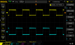
From what I am seeing the feedback is oscillating and you need to dump it. You can try a small capacitor across the zener diodes. (10nf-30nF) You also need to load a little the output. You can also try a different capacitor in the compensating pin 9 SG3525. I myself ended up with 10nF across 470K resistor instead of 68nF to get a good result.
What you are seeing is discontinuous mode as probably the output is without load. Having a minimum load is important in regulated smps. You also need to snub the output diode across the secondary winding, this because the output inductor will create spikes which will reflect in the primary windings and the auxiliary.
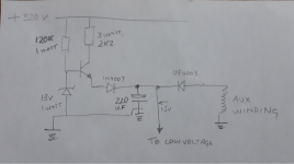
One last thing. Due to the smps is working at different loads you definitely need a stand alone auxiliary psu as with light loads you may not have enough voltage produced by the auxiliary winding due to the pulse width will still be very narrow. The start up circuit I posted yesterday is not meant to stay on more than a few seconds.

here is a link for you to see what I done regarding the feedback. Download the pdf to see the schematic.
 
Yes, I will be adding an auxiliary power supply. From what I've read, the SG is not really capable of starting up like a UC3843 does (it maybe can but the resistor has to handle the whole supply current).
 

Silvio

Well-known member
Yes, I will be adding an auxiliary power supply. From what I've read, the SG is not really capable of starting up like a UC3843 does (it maybe can but the resistor has to handle the whole supply current).
Yes it has to that is why i suggested a stronger start up. If the smps was unregulated then the pulse width will be at maximum and the auxiliary voltage will hold strong' in your case it is regulated and the narrow pulse cannot sustain the voltage when the smps is unloaded. Yet another way to feed with a resistor is to feed it from the ac line and use a single diode thus having around 110v dc. This will minimize dissipation. This still only be good when the smps is either working with a constant load or at full duty pulse. With no load is very difficult to sustain the auxiliary voltage when regulation is in use.
 
Top