Llc hb smps 2000w

Silvio

Well-known member
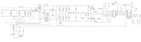
Here is an smps that I have been working on for the last 6 months. This is my first prototype and apart from the simplicity this smps has a lot of features for it to work on an audio amplifier.

1) Over input voltage protection with a Varistor

2) A good input filter to reduce EMI as much as possible

3) Generous input and output capacitance 2700uF in the 320v input and 10,000uF on the output

4) A good soft start design

5) A good short circuit protection which is self reset after 3 seconds and turns to hiccup mode if the short is still present. Eventually it will turn to thermal protection sensing the heat on the soft start resistors.

6) Thermal protection with a normally open bi-metal switch on the IGBT heat sink

7) Temperature controlled fan speed for 3 X 12v 80mm fans.

8) Being LLC has a sinusoidal current wave form. This helps a lot in reducing EMI and noise

9) From my initial tests it seems very promising and very strong.

10) The SMPS peaked 2300w with a modest voltage drop of 11% on the output voltage.

11) The power factor was 0.65 with no load and 0.98 at full load.

12) The efficiency reached around 89%

13) Lastly the fuse was omitted from the PCB as this is to be attached on the amp chassis.

2000w smps 1.JPG2000w smps 2.JPG2000w smps 3.JPG2000w smps 4.JPG2000w smps 5.JPG
 
Last edited:

Silvio

Well-known member
Not really its 100% my design and i spent a lot of time perfecting each section so that i will have a reliable smps.
In my early versions I had a problem with start up issues. Now it can start facing a 1.5 Kw or more load. The smps is true 2K which can be sustained for 10 min at cont load with propper cooling. Its size is quite small for its power being 18 x 22cm. I might share it but with a different control circuit that use Ir 2153 chip. The SC will be latching type not auto reset. I may also include the thermal protection aswell.
 

res_smps

Member
I might share it but with a different control circuit that use Ir 2153 chip. The SC will be latching type not auto reset. I may also include the thermal protection aswell.

I am happy that you also developed a resonant smps and shared it here because all this time I felt alone (only a few were interested) to learn resonant smps. Initially I learned LLC Resonant Smps from the application note from IRS27951 and performed a simulation using IR2153. I have ltspice model ir2153 and llc smps simulation, do you need it?
 

Silvio

Well-known member
I am happy that you also developed a resonant smps and shared it here because all this time I felt alone (only a few were interested) to learn resonant smps. Initially I learned LLC Resonant Smps from the application note from IRS27951 and performed a simulation using IR2153. I have ltspice model ir2153 and llc smps simulation, do you need it?

Thanks for the offer RES but I do not have spice simulation. I always try the real thing that is where I get my results. I have been developing this smps for the last 6 months a bit by bit, The oscillator and protection was the big headache but finally I succeeded in using a voltage comparator sensing both high an low side pulse. The LLC inductor doubles for current sense and added inductance needed for LLC operation. I made a two turn coupling loop around the LLC inductor PS not all cores work here it has to be those brown ones that I find to work well. I did not have a large one so I stacked 2 of them together. That is why it looks longish. I had to use a snubber on this as well to tame down the spikes it creates. The second task was to create a small delay when it comes to reset on the 555 timer but I did some reserch and took a few ideas and I managed to create it as well. The last thing was the thermal shut off which I did with a few transistors creating the initial relay delay on soft start and thermal shut down combined together. These are partly on the main pcb.

Summing up and gathering everything together was my last task so that in the event of breakdown the main pin header was easily pulled out and repaired. The pin header came out a bit high as it is on a single sided pcb. I already designed one in smd which this will sit flush with the same height of the bulk capacitors.

Pin header in smd
View attachment 6975
 

res_smps

Member
not all cores work here it has to be those brown ones that I find to work well. I did not have a large one so I stacked 2 of them together. That is why it looks longish.
I use an iron core that is commonly used for class d output inductors
 

Silvio

Well-known member
I use an iron core that is commonly used for class d output inductors

In fact that is what I used. The permeability has to be very low. Other types do not seem to work and tend to generate a lot of spikes. Even the waveform across the core seems to change with an unsuitable core material.
 
Last edited:

MyFirstSMPS

New member
Which controller you used? Seems like SG3525 + IR2110 gd or I am wrong?
Probably you dont want share circuit but without a components values maybe?
 

Silvio

Well-known member
Yes I used SG3525 and IR2110. I may share the circuit with a different controller. The one I made is quite advanced and is not straightforward. I am working on a different control with IR2153 but you have to wait a bit more as I am not finished yet. There is still some more tests to be made and modifications for correct operation. I like to use IR2110 as a mosfet or IGBT driver as this has a logic input and always produce a nice waveform. Regarding isolation a pulse trafo is better though but this has to be suitably made otherwise the sg3525 tend to produce overshoot on the square wave. The pulse trafo tend to produce ringing as well when driven hard. You see there are advantages and disadvantages. Clean waveforms are important to eliminate EMI. I guess you saw the screen shots of the waveform in the youtube video. A good input capacitance is also necessary to minimise ripple and voltage drop at load. In my 2k smps I use 2500uF across 320v in the input. At least that is what I see in commercial pro amplifiers.

Regards Silvio
 

MyFirstSMPS

New member
I think that this 2500uF is more better than most of commercial amplifiers. Do you have tried also DC-LINK FILM capacitors? If you use this then you need much smaller capacitance.

I know IR2153 and IR2156 and previously built some this design which is also good. I have as well SG3525+IR2110+IGBT project in progress :)
And next I want to try UC2825+gdt+MOSFET and also +IGBT.
 

Silvio

Well-known member
I think that this 2500uF is more better than most of commercial amplifiers. Do you have tried also DC-LINK FILM capacitors? If you use this then you need much smaller capacitance.

In my case things are a bit different as I am smoothing the 320v rail then dividing the voltage with a couple of film 1uF capacitors. The latter mainly get all the beating from the reserve capacitance (the Electrolytic caps). As far as EMI I got a double stage filter tuned to the frequency of operation and its harmonics. Apart from all this I also added the safety capacitors between Phase and earth ground and neutral to earth ground. There are also capacitors shunting HV ground to earth ground on both sides of the HV negative trace to shunt out any noise to ground. Beside all this I also got a 1uf across the 320v and also a 2.2nF across the HV positive and negative. I tired to take all the precautions to eliminate EMI as much as possible. If you notice well in my design I am to add a piece of sheet metal to cover and completely shield the input filter to eliminate EMI. I am not sure what the top cover of the input filter will be if its to be a solid sheet or a perforated one to help with air circulation. My heat sinks are all earth grounded in various places and not on a single point. Finally the brass standoffs holding the PCB on the bottom will be bolted to the chassis of the amplifier box.
 

Silvio

Well-known member
A few tips for you when designing the pcb

It is important that the drive circuit will have the traces as short and thick as possible. I used a vertical pin header to keep away as much as possible from high current paths. These tend to disturb the pulses going to the gates picking up stray inductance and stray capacitance. De-coupling near each IC on the control pcb is also important. At high currents anything can happen. I got a good result as you can see from the screen shots of the wave forms across the main transformer, they are very clean even at high load. Usually decoupling is made with 2 capacitors one being electrolytic of around 10 to 22uf and a parallel 100nf ceramic or film. Lastly pcb trace clearance is important for safety. At mains voltage 230 VAC 3mm is kept all the way and 4mm at the 320 DC rail. When this cannot be achieved a slot in the pcb will do the trick. Look closely at the pics on the youtube vid and you will see some slots near the input filter. Trace width is also important and this must be 1mm per ampere of current, in my case 15 amps where calculated on the output and 8 amps on the 320v rail. Where it was not possible I added 0.5mm solid copper wire and soldered to the copper trace to help out with current handling and eliminate voltage drop.
 

MyFirstSMPS

New member
OK. Thanks for the tips (Y)
I have a previous experiences but thanks anyway.
I meant this DC link - that maybe you've tried to replace huge electrolytic filtering caps for DC-link film capacitors, but probably not yet.
And against this EMI - I have seen example some Parsec MarkBass guitar combo amp which has been used filtering almost the same way, they are for example covered this DC filter elcos with copper foil, it is about maybe 0.2mm thick and it is twisted around capacitors and grounded one edge.


Is your circuit is something like this?
 

Attachments

  • SMPS52.jpg
    SMPS52.jpg
    128.7 KB · Views: 101

res_smps

Member
OK. Thanks for the tips (Y)
I have a previous experiences but thanks anyway.
I meant this DC link - that maybe you've tried to replace huge electrolytic filtering caps for DC-link film capacitors, but probably not yet.
And against this EMI - I have seen example some Parsec MarkBass guitar combo amp which has been used filtering almost the same way, they are for example covered this DC filter elcos with copper foil, it is about maybe 0.2mm thick and it is twisted around capacitors and grounded one edge.


Is your circuit is something like this?
can you show in the schematic what is meant by the dc link capacitor?
 

Silvio

Well-known member
OK. Thanks for the tips (Y)
I have a previous experiences but thanks anyway.
I meant this DC link - that maybe you've tried to replace huge electrolytic filtering caps for DC-link film capacitors, but probably not yet.
And against this EMI - I have seen example some Parsec MarkBass guitar combo amp which has been used filtering almost the same way, they are for example covered this DC filter elcos with copper foil, it is about maybe 0.2mm thick and it is twisted around capacitors and grounded one edge.


Is your circuit is something like this?

Yes more or less but it has more to it regarding initial soft start and protection.

I tried to look for what exactly a DC link capacitor is. If I understood correctly it is a huge film capacitor maybe in a round shape with bolted terminations and in the picture the capacitance was 150uf and 100uF. Can you please explain how they are used and what is the benefit of using them instead of electrolytic caps.

I found this pdf and did not clearly understood if you use them instead of electrolytic caps. I can see that they are more reliable but regarding the ripple current do you need the same capacitance as electrolytic or less using them.

https://www.electrocube.com/documents/DC_Link_Tech_Bulletin_vF_092816.pdf
 
Top