Looking for a DIY Smps for my 9ch highpower amp

Stian

New member
Hi all!

Im looking for a smps that can deliver me about 25A at +-70-80v DC.

Im running it with ordinary transformers to day, it works good enougth, but it requires a good damn ****load of capacitors to be able to preform at an optimal level, and i think a big (or a few in parrallel?) SMPS would give alot better results performance. Ripple is to big today.

Now, what design do you recommend for this? I see there is a 1kw project and a 4kw project(with very little information) in sticky in the forums here. The 1kw seems to be a little more detailed, but i would require 3 maybe 4 units in parrall with each other to reach full power.

The maximum dimensions will be LxBxH 400x160x80mm.

My english is not to good, but i hope you understand
Thank you,
Stian
 

Stian

New member
Time for a update.

I have spoken to microsim on the forums and he has given me some help regarding this smps, but my messenger stoped working and microsim wouldnt answer on mail, so then i rather ask on the forums and maybe get even more inputs ! :)
I just blow my first set of IGBT`s today :eek: On a prototype board using IR2153 as a driver IR2153 Prototype schematic. Transformer used was ETD59 N87 with 8 windings 0,1mm x 120 litz primary.
It gave me around 200w output at a input of 70V. IGBT`s never got seriously hot, but the rectifiers on secondary side did get very hot, MUR 16A Diodes. The output signal from IGBT`s looked veryvery bad:
Signal1
4ohm load
Output:
7,14A
30,1V
= 215w
Input:
4,24A
71V
= 301w

Signal2 - 8ohm load
I was about to test with 16ohm load and take some screenshots of it, but then the igbt`s where blown.
Without any load, signal looks perfectly nice, like a square wave should do. With 47ohm load it also looked nicely(about 20w).

But, it was really not this one i thought about talking about. It was rather the real one im working with. IR2153 one was rather just one to.. ehm, see if i can get it working rather... hehe..
This one is based on tips from Microsim, and some of Luka`s work on his SMPS + a pair picups here and there. Aux supply is not shown, but it will be one made from tinyswitch modules. Current sens board is not shown either, still not even made, some tips here maybe??? :D
Frequency generator and driver is placed on a seperateboard placed verticali on smps board for space savings. Same will most likely be with currentsensor and tinyswitch board, unless someone has a no no no on that? :)
Frequency generator and driver is just a pure copy of Luka`s smps for now. Some notes on changes for this one?
This is schematics for my work so far:
2kw SMPS
Luka Frequency and driver

Any tips or thougths to give?
C3 on 2kwsmps, would 2u2 hold for this application? i see some even use 6x 2u2 for about same poweroutput. And should it be placed after IGBT`s or after Caps(why?)?

Thank you all,
Stian
 
Last edited:

MicrosiM

Administrator
Staff member
Smps

Sian

I am sorry for not responding to mails, I am too busy, But now I am Ok

That test you made was a mistake, I told you to ask me step by step. No problem


Please show me prototype you made, (Upload to Forums) rather than linking

Those Scope waves, at witch points?

LUDO already made that SMPS, with PCB layout, and he succeeded into it 100%

Here it is again,
http://www.diysmps.com/forums/showthread.php?79-1kW-smps-project-(based-on-MicrosiM-design)/page6


I am now free to give you help again

Show me some results
 

Stian

New member
Hi sami!

I understand you are busy, i am too from time to time :)
And by asking on the forums, i maybe even get more inputs :)

That test you made was a mistake, I told you to ask me step by step. No problem
Why was that a mistake?

Please show me prototype you made, (Upload to Forums) rather than linking
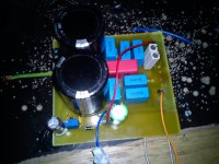
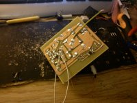
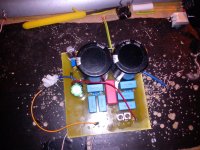
Uploaded some photo`s of it. ETD59 and rectifiers is placed externaly and wire between ETD59 and prototype board is litz, so should not cause to much of trouble. IR2153 is SO8 device. BUT, ETD59 is not winded for 70V DC, maybe this is why its acting up? With your calculator, i got around 12-13 rounds(i believe, i checked last night but i cannot remember the exact results, at 320VDC) it is at the moment winded with 8 rounds

Those Scope waves, at witch points?
Those where at both ends of primary side of ETD59
 

Attachments

  • DSC00193.jpg
    DSC00193.jpg
    198.8 KB · Views: 125
  • DSC00200.jpg
    DSC00200.jpg
    200.4 KB · Views: 90
  • DSC00195.jpg
    DSC00195.jpg
    259.5 KB · Views: 90

MicrosiM

Administrator
Staff member
Blow up

Its very normal to blow IGBTs with that Kind Of PCB and setup

It was much easier for you to make Ludos Layout, and u had succeeded.

Special routing is required for SMPS in general, PCB Layout

I have no idea if you are using proper parts also, IR2153D is tricky of its kind as SMPS

Check Ludo SMPS schematic, You may missed something, Also Make his PCB, I posted last version there
 

Stian

New member
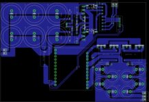
What do you think about this layout?

Aux supply is not added yet

Btw, ive reinstalled windows and yahoo is working microsim !! :D


EDIT: Hi-res image
 

Attachments

  • Board.jpg
    Board.jpg
    20.2 KB · Views: 112
Last edited:
Top