PIC logic analyzer - digital storage oscilloscope

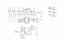
Being curious about logic analyzers and pc based oscilloscopes, I started researching a little bit. I had initially looked at the bitscope oscilloscope. The original bitscope based on 16F84 and then the BS300 which have their schematics published gave me some ideas. The solution is based on a hardware and pc based software combination. The hardware for a logic analyzer based on a buffer connected to a SRAM chip. The microcontroller controls the address when data is stored in the SRAM and then sends everything to a pc. There is a second non electronic and less DIY friendly which is the pc software. I have successfully obtained/built the following:-

1) CD4050 buffer- max 15V input
2) HM62256 32K x 8 bit RAM- Allows to create a 8 channel 32K buffer logic analyzer
3) C#.NET based application using MSchartcontrol of type line with a max Y-Axis limit of 1 and low limit of zero that can read serial ports(I am using FTDI serial to USB conversion for the time being)

I need to fit all the above together but the software with a simple serial dump from the microcontroller worked.

Whats needed to turn the above into a pc based DSO is a TLC5540 75MHz bandwidth 8 bit ADC capable of 40MSps () in a combination with a vertical buffer connected to the CD4050 buffer, change the graph to match the vertical sensitivity.

All this does not seem impossible but I will keep it as a logic analyzer first and then consider the DSO.

The are simpler implementations like the DPscope which I consider to prototype and see what happends

I'll keep posted
 
Basic C# serial communication app

I have successfully built a small C# application that receives the data being sent by the pic over a CP3102 serial to USB converter. Attached is a picture of the working app. There seems to be an issue with the disconnection which I need to fix otherwise it worked straight from start. C# serial app.JPG
 
I have been able t successfully solved the issue with the disconnection it was due to the thread issue between the UI and the serial class in C#. I am now able to echo character sent from my C# app to the microcontroller back to my C# app. Next step is a protocol build up
 
Working Logic analyzer

Attached in a sample screen shot of the working logic analyzer software Working analyzer.jpg. For the time being the capture is done and sent to the pc @ 115200 Baud without any buffering. I am still working with the HM62256 RAM. I need to figure out why I am not getting the value I am writing to a location but that should be simple to solve either its the signals/timing or my breadboard connections. I will keep posted
 
Schematic

Attached is the real time analyzer schematic. I am going to build it on stripboard just to have something more stable to work with. I'll keep posted. It lacks input protection diodes which I will add later
 

Attachments

  • PIC16F628A Logic Analyzer.jpg
    PIC16F628A Logic Analyzer.jpg
    130.8 KB · Views: 62
Last edited:
Protoype logic analyzer

After some issues with reading ports and some others in clearing the data on my charts, i finally got the logic analyser to a stand alone prototype. Its a slow device i am working with right now but i think things look promising. Currently the serial port is stable at 115200 Kbps and all it does is when it receives the character c the ports are sampled, time is incremented and the whole is sent in the format PORTData Time; continuosly until the stop character is sent. While data is being sent the C# software cumulates data in memory and when is sent, the data is transformed and displayed on a C# chart control. I am currently sampling >3000 port reads per seconds including time required to transform and send the data to the FTDI. Its very far off the 24 mega sample sent by some pc based logic analyzer but with some more hard work i should get there. The pic is currently clocked with a 20MHz crystal and working at 5MHz. Upgrading to an STM32F103RBT6 working at 72MHz should make a huge difference but its not for now. The next step is not use this prototype to help me debug the issues i am having with the HM62256 chip. The attached pic shows the prototpe its ugly and dirty but it works. At the top is the CD4050BE, mid is the 16F628A and bottom is a MAX232 and the serial port to which a serial to USB converter is connected. The side board is a 7805 regulator. Deriving power from the RS232 port did not prove successful but direct USB power should solve that since the circuit consumes only 3mA of current.
 

Attachments

  • Photo-0158[1].jpg
    Photo-0158[1].jpg
    183.1 KB · Views: 37
HM62256 working

I did some test with my prototype and the waveforms showed a lot of losses even for a 5KHz signal. But at leat that helped to stabilize the pc software and solve some instability issues i was getting on input. I managed to get the HM62256 to work. The issue was that i was using PORTB and the debugger was connected to it. I shifted to use 2 74HC595 shift registers for the address and it worked like a charm. I am thinking of reorganizing my Address and datalines around the pic and see if i can do without the 74HC595 for the time being since i want a stand alone analyzer and then i'll see for the scope. Am also wondering since i got 2X HM62256 whether to go for 16 channels and each channel is buffered to an HM62256 for 265K storage or parallel 2 HM62256 and stay with 8 channels but 512K storage. An idea also came to my mind to have both at the same time and have the software control it. I'll see how well it works with one HM62256 and decide afterwards.
 
Improvement with the real time analyzer

I gave the 16F628A version another try. I have stopped sampling time and aimed only for the data. There seems to be a compromise to be made between buffer size, signal frequency and compiler operation mode. I am currently using a 80 bytes array to capture PORTA and using only RA0-RA4 attached are the waveforms captured in lite mode (free mode) and pro mode (which can be activated for limited time) for a 100KHz signal. I am currently using the signal coming off a probe adjustment pin on a DSO nano. The HM62256 is still on but I am getting heavy interference on the data pins which I need to terminate most probably to solve the issue. I will keep posted100KHz Lite mode.JPG100KHz PRO mode.JPG
 
16F628A schematics

16F628A logic analyzer.JPG This is the unit I used to get the results I mentioned. In the meantime I will be trying the same approach with a STM32VL board and compare the results. Then i'll go back to solve my HM62256A stray noise issues.
 
Some updates on the project. I have been using IAR EWARM with the STM32VL board. I ran into an issue in trying to achieve the same functionality i.e. capture, transform and send until interrupted. The issue could either be the speed of the GPIO or the way the library handles transforming a port read value into text. I got some blank output. At first i though it was the GPIO not communicating fast enough with the CPU and tried DMA access to store the data read, but still it did not solve the issue i left it aside and went to handle the HM62256A.

I don't know if its a good sign if you get the same issue some other designers ran into and you are on the right track but this is what happened with the HM62526; I tried to control the memory address ports through a shift register (serial to parallel). The issue was that the speed of capture was worse than with the pic16F628A. Instead of trying to control the memory directly with the pic(that would require 14 address lines, 8 data lines and 3 control lines YES!!!) i am going for something different. I am going to use a pierce oscillator based on a crystal oscillator. This oscillator will then connect to a 14 line ripple counter. I have built and tested the pierce oscillator based on a CD4011 and successfully acheived 4MHZ clock(though dirty but it should do the job). I am waiting for some 74HC00 to arrive which should get me higher in the MHz sampling speed. In the end i am trying to achieve 20MHz sampling speed which sends me to 20MSa/Sec. For capturing the oscillator will run and drive the ripple counter and hence memory addresses. However the issue is reading. The microcontroller will need to be synchronized to the clock for reading. I will either use the pierce oscillator and interrupt it or send a separate clock for reading my experience right now with pic and STM32F have not been very succsful at high speed.

Otherwise for those of you reading the post , the way the products out there do it is through a CPLD to act as memory controller, i like to learn new things but this is not the time to dive into VHDL programming, buy a CPLD + programmer and take a month to get the whole thing working. Plus the free dev tools from Xilinx and Altera seem highly limited. I'll keep posted
 
Last edited:
some more updates I have been able to get an STM32F103RBT6 to work with USB. I have used the USB HID example provided by IAR and the code runs on EWARM. I had to modify the following files:
hw_config
platform_config
usb_desc

The reason I used HID is that no driver is needed. There is one major area that's a head ache and it is about the report descriptor. I had to use a tool from usb.org that can generate report descriptors, copied and pasted and it worked.
Another issue I also ran into is that I cold not get a good c# library to build the pc client. I had to use java and a library called usb4java and now communication flows nicely from the STM32f103 to the pc. The downside is that now I have to rewrite all my logic analyzer functions and interface in java.

I also completed the code to build a memory controller on a EPM240T100C5 using VHDL. The setup should be as follows:
Input->Buffer->HM62256<-EPM240T100C5<-STM32F103RBT6->USB->PC

The STM will control the CPLD which in turn will control the RAM. Next step is to build a pierce oscillator to act as signal clock for the EPM240 to control the memory address. I will keep posted. Any input is welcome
 

mikejp56

New member
PIC Logic Analyzer

Hi zeus_threat,
I found your project and I am very interested in building one. I will follow your progress, and when I start to build my own I will keep you posted here.
Regards,
mike
 
Top