SMPS with PFC

Silvio

Well-known member
Hi Michelle, I forgot to mention something else. If the smps is to be a 2Kw one then the input capacitance shall be larger. A couple of 680uF or better still 1000 uF at 450v will be a better choice. However the 1000uf capacitors tend to be longer and they may not fit in the amplifier box. The aim is to have at least 1uF per watt of power.
 

rinchz

New member
HB PFC's

Hi Michelle, I forgot to mention something else. If the smps is to be a 2Kw one then the input capacitance shall be larger. A couple of 680uF or better still 1000 uF at 450v will be a better choice. However the 1000uf capacitors tend to be longer and they may not fit in the amplifier box. The aim is to have at least 1uF per watt of power.

hi sir i have learned a lo from you since, thank you very much
i have seen these SMPS schema a little long time and i am interested in doing so, things that hinders me was i am so busy at times to do my hobby but i have assessed these files and extracted top and bottom layout i am a poor guy so i plan to DIY the PCB side or re-layout in a 1 sided PCB.
1. may i ask another question i have seen 3x470uf/450v and a lot of output caps, will these be suitable for 2KVA or 4KVA (ref to other layout) SMPS'
2. if i may i have plenty of 680uf/400v can i use it? i also have 2200u/200v on reserved.
3. i have sanken b2 from sony led tv PSU i think i can use it for aux supply.
4. my only problem on these layout were the correct details of GDT core and windings...
and i will be subscribing on these because i will be doing it soon.

thank you very much...
regards
 

Silvio

Well-known member
@ Rinchz,

Regarding the PCB you can design your own if you want and make one in single sided version. Take care of the spacing between traces when it comes to the high voltage ones. 3mm in the mains input and 4mm on the bus traces carrying 400VDC or more. The trace width is also to be considered and this is calculated at 1mm per amp for a 1 ounce copper clad board. Where this spacing is not possible to be maintained all along then a slot of 1.5mm in the pcb can be cut instead in these tight areas. Keep in mind to keep the traces carrying high current to be as short as possible and also try to keep the signal lines away as possible from high current paths. A vertical pin header pcb is a good choice to save space and keeping away from stray capacitance and inductance. This will carry your control chip and mosfet driver.

Regarding the input capacitance you can use either the 200v ones but the capacitance will be half. 1uF per watt means that this is across the 420v rail. To keep it simple this mean that if you have 2 capacitors of 1000uf X 200v then the value of the input capacitance will be 500uF x 400v rating. If on the other hand you have capacitors of 400v rating then this can be put across the bus directly and then use smaller divider capacitors for the half bridge. The divider capacitor value will vary according to the load absorbed by the smps. Usually they be between 0.5uf and 3uf rated at 400v. normally we use film capacitors or MKP or CBB capacitors.

As for output capacitors well for 2KW usually around 4 to 5000uF per rail will suffice. ESR is most important here so good quality capacitors must be used.

If a pulse transformer is used in the case of a full bridge arrangement then a small core with high permeability is chosen. This will have its windings in parallel (5 in this case) wound with CAT 5E or Cat 6 wires for better insulation. This wire is usually found in data cables used for computers. The number of turns has to be found regarding the requirement of the total inductance wanted. It is quite practical to wind a number of turns on the core and measure in inductance until the number of turns will be found. It is good practice to fit the parallel windings in a single layer and the wires will be of equal length. Symmetry in the windings is important in this case.

Another approach is to use 2 mosfet drivers (IR2110 for example) instead of the pulse transformer. A pulse transformer will produce better insulation but if not carefully designed the wave form tend to change, however if a mosfet driver is used then these have logic inputs and produce very nice waveforms from their outputs.

An auxiliary supply can be readily used as long as it has enough power (8 to 15w) usually suffice. Be sure it has good smoothing and regulation at the output.

Regards Silvio
 

res_smps

Member
Sorry Silvio,
With the presence of PFC, capacitor requirements can be smaller, I attach an excel file for PFC calculations (I downloaded from onsemi website) in post # 5
I have never built / haven't been interested in using PFC because for residential users (here) the power factor issue is not regulated by the government.
And I think (maybe i'm wrong) for home audio with small power, PFC will add one more (besides the pwm chip) high frequency noise source
 
Last edited:

Silvio

Well-known member
@ Res,
Yes it could be that input capacitance can be smaller and it is also true that there is another high frequency noise source. This chap is building a 4Kw smps. Only one thing is concerning me though if a PFC stage is omitted at this power you know better than me that the input of the smps is highly capacitive (capacitive reactance). I am just wondering where is the extra current that shows on the ampere meter is going?
I explain myself better. If you had to use a wattmeter in the input when loading an smps you will get a certain power reading. If you had to use an ampere meter and a voltmeter and add these up you will find that the power calculated is much greater due to the PF being around 0.6 or so.

I await your opinion
 

res_smps

Member
Dear Silvio,

First I clarify my statement above that I do not need (interested) the PFC applies to me personally, not in general.

from what I understand, reactive power only circulating in system, in one cycle at a short time a large current is needed to charge the capacitor and supply the load, but in the remaining time cycle the capacitor will transfer energy to the load.
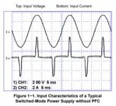
smps without pfc.jpg
(source : PFC handbook by onsemi)
but this peak current is seen by the circuit breaker, not good for power lines and for electricity provider.
Please correct me if I am wrong

I think this will be an interesting open discussion :
1. Sometimes I think whether the reason for big manufacturing is not using PFC, is it only because of price issue?
2. Does the regulation (American or European) not force amplifier manufacturers to use PFC?
3. Is it because in a building there is usually a power factor correction system?

I made a list of amplifiers that use smps below :
most of them use "The legendary chip" like TL494 and SG3525, same designer?
only class D from yamaha (XMV8140)uses PFC

1. Yamaha
– Yamaha EMX5000 : Halfbridge, unregulated, IR2153
– XMV8140 (class D IRS2092) : halfbridge, unregulated, SG3525 with PFC
– T5n (EEEngine) : halfbridge, unregulated, SG3525
– XP5000 (EEEngine) : halfbridge, unregulated, SG3525
– PC9501 (EEEngine) : halfbridge, unregulated, SG3525
– YST-SW800 : self oscillating, halfbridge, unregulated

2. C-audio
– Pulse series : halfbridge, unregulated, SG3525, discontinuous resonant

3. Crown
– CTS 4200A : halfbridge, unregulated, SG3525
-CTS600, CTS1200 : halfbridge, regulated, UC3846
-CDi2000 : halfbridge, unregulated, TL494
-XTi4000 : halfbridge, unregulated, TL494
-XLS2500 : halfbridge, unregulated, FAN7387
-CE4000 : fullbridge, unregulated, UCC3895DW, PFC

4. Labgruppen
– Fp3400 : flyback, unregulated, UC3851
– Lab4000 : flyback, unregulated, UC3851
– FP10000q: TD class, flyback, unregulated

5. QSC
– PLX series (PLX-1202): halfbridge, unregulated, SG3525
– Powerlight Series : halfbridge, unregulated, SG3525

6. NAD
– M22 : halfbridge, unregulated, synchronous rectifier, TL494

7. BEHRINGER
– PMP500 : SPS1000, halfbridge, unregulated, IR2153
– SMPSU18 : halfbridge, unregulated, SG3525

8. CARVIN
– BX1500 : halfbridge, unregulated, resonant, IR2153

9. Mackie FRS2800
- halfbridge, unregulated, KA3525

regards,
res
 

Silvio

Well-known member
Hi Res, I was taught that Power factor is not measured by the watt meter when I was getting my A electrical licence. But still the extra current drawn from an appliance due to bad power factor will load the cables unnecessarily. The teacher said that if a factory had a long line of neon tubes (which in those days used a normal inductive ballast) would have a lot of inductive reactance. This was corrected by putting a small capacitor (5uF for a 40w tube and 8uF for a 65w tube) would correct the power factor near unity. He even said that at times they had to put also a power factor correction near the distribution board.

Nowadays we are experiencing the opposite with LED lamps and electronic ballast etc. This in turn need to be corrected with inductive reactance which is not so easy to implement especially if the load is high. Another case that I know of was when a long LED festoon was installed along one of the promenades on the island and the electrical section at work where having trouble with the MCB tripping for no reason. When the load was calculated the result of the current was way below the MCB rating thus due to bad power factor this time (capacitive reactance) it was hard to solve the problem as the cost of such a series inductor was quite costly, however they solved the problem by dividing the festoon on more MCBs.

With all this in mind I was concerned if the switching transistors in an smps was also carrying this extra current.

What you said is all true about Pro amplifier manufacturers they all have a bad power factor. At least since I am repairing these this is what I find in those amplifiers using an SMPS as a power supply.

I tested these so far
Crown CTS 2000 and also 3000
American audio 1200
Nova
Behringer 1000
Master audio HPA5000
Audac
LD systems
Tasso
some active speakers like JBL and also Wharfdale etc

There are a few more but cannot remember right now.

Regards Silvio
 

rinchz

New member
Hello Silvio
greetings i have ordered the pcbs from jlpcb now i am ordering the parts can you identify IC 1
8pin soic smd beneath the pcb bottom layer
warm regards
Michelle

hi there sir how was your order is it the 2KVA you have ordered? or do you have gerber files of 4KVA also?

thanks
 

Silvio

Well-known member
Yes he is he also contact me. You have some mistake in schematic regarding inductance value of aux power supply I think you reversed the values primary with secondary. Also the primary inductance should be around 2mH or so.
 

res_smps

Member
Yes he is he also contact me. You have some mistake in schematic regarding inductance value of aux power supply I think you reversed the values primary with secondary. Also the primary inductance should be around 2mH or so.

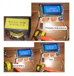
I measured the inductance of this Sanken transformer which turned out to be quite small, I have never used it so I cannot comment further
Lp : 152.8uH
aux 9.68uH
Ls (out) : 15.89uH
sanken trafo.jpg

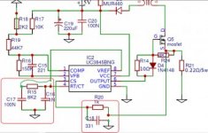
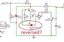
I also found some mistakes
schematic error.jpg
 

rinchz

New member
PCB mistakes?
View attachment 7104

ordered 2kva pcbs

greetings...
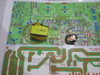
i think rookiex have ordered 2kVA trafo where those mistakes are not present in 2kVA HB PFC schematic. i also observed those difference in a 4kVA schematic using GDT but i am not in a position to critic,

i have also here some sanken B2 trafo from 60watt TV adapter (19.5v 3.4xA) a little too big for the space it measures differently Lp-53.2uH & Ls-30uH and another hipro 30watt Adapter (19v 1.58A) measures Lp-1.015mH & Ls 0.037mH. IMG_7615.jpg

thanks
regards
 

res_smps

Member
i have also here some sanken B2 trafo from 60watt TV adapter (19.5v 3.4xA) a little too big for the space it measures differently Lp-53.2uH & Ls-30uH
What controller IC is used on this adapter?
does it work with a quasi resonant flyback?
 
Top