Tl494 smps

noorworkshop

New member
Hi all

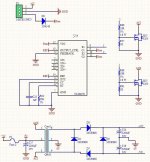
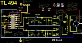
I made TL494 push pull Smps for car amp(No feedback)
my test amp is 100w.

i tested with AWG26 wire and output Dropped from 32 to 17 volt in 60% music volume

core information
pri:5+5 turns(17 Layer)
sec:13+13 turns(7 layer)
i Calculate for 200w smps power.(Double AMP power)

but there is a lot of voltage drop.

i try to use AWG18(~1mm wire) or Thicker wire for core of smps to have less layer but I do not know the current of any wire.
And how to avoid switching voltage drop

please help me
thanks
 
Last edited:

noorworkshop

New member
Smps

This is my core for 200w smps power (100w amp power):
photo_۲۰۱۷-۱۱-۱۷_۱۱-۲۳-&.jpg


and this is for 4x80w Marshall Amplifier:
photo_2017.jpg

How is the core computation of the converter??
(Which is the size of the wire too small (the wire thickness is higher) and its low drop)

Circuit Frequency is 32Khz but i can change it(if needed)
 
Last edited:

Silvio

Well-known member
@Noorworkshop.
1) Please upload schematic so that we can see why is the large voltage drop you are experiencing.
2) What type of material the core has? EX. Epcos N87 etc.
3) What dimensions the core has? (inside dia, outside dia, thickness).
4) If you changed any components such as different transistors etc please specify.

We will try to help you the best we could to make a successful smps.

Regards, Silvio
 

noorworkshop

New member
Dear Silvio

its my schematic(in test i use irfz44 fets).

core name is OR38.
inside dia:~22mm
outside dia:~38mm
thickness:15mm

i just change fets from IRF3205 To IRFZ44.

thank you for help.
 

Attachments

  • shc.jpg
    shc.jpg
    83 KB · Views: 146

Silvio

Well-known member
Switching frequency 27Khz Topology push pull 32-0-32 (64v @ 3.5A) = 224 watts
Primary turns 4+4
Wire gauge AWG 20 0.8mm
Number of strands for primary 4 wires
current in primary winding around 18 amps at 200 watts load (current density @ 6 Amps per mm²)

Start from center tap with 8 wires in hand and wind together ( you can glue bundle of 4 wires side by side to make life easier) Distribute evenly around the core and keep symmetry as much as possible.

secondary turns 11+11
number of strands 1


The voltage in the secondary can rise a little due to the car battery being charged when the vehicle is running and the input voltage can rise up to 14 volts, However with this input voltage the secondary voltage also rises a bit and can go up to 38v
If your amp cannot take up till 38v you can lessen one or two turns on the secondary, The volts per turn is 3.25v

Mosfets. the IRF3205 is better than IRFz44

Winding practice. Use symmetry as much as you can during winding. You will be better off starting with the secondary first and then after taping it up (use Mylar tape two layers). For secondary start with 2 wires in your hand and that start will be the center tap, You will finish your turns together with the 2 wires, You will put the ends of these the wires to the input of the output bridge rectifier. the center tap with 2 wires will be the ground. Distribute the wires evenly around the core.

Tip You can align the wires side by side and tighten them up, when aligned perfectly you can stick them together with some super glue, This will help out during winding.

I hope you have a better idea what current is involved in the primary circuit, and it may be the winding not being symmetrical that you are experiencing voltage drop. It could also be the fets having larger resistance (IRFZ44) than the the ones suggested in your schematic. Be sure to use adequate wire gauge to handle the current on the primary circuit,

Regards Silvio
 
Last edited:

Silvio

Well-known member
@Noorworkshop

Regarding the mosfets if you are using IRFZ44 then you have to parallel 2 on each side. This is due that the RDS of the IRfZ44 is higher than the IRF3025.

RDS for IRFZ44 is 0.022 ohms while the RDS of the IRF3205 is only 0.008 ohms.

In case you are using 2 transistors (IRFZ44) on each leg then change also the gate resistors from 10 to 22 ohms so that the equivalent resistance will be seen by the TL494.

The reason behind all this is that there is too much voltage drop when using IRFz44 but you can overcome this problem by using transistors in parallel to overcome this problem.

Regarding the last post you did not tell me the core material and the calculations are for PC40 ferrite. If by any chance you may know it than post back and I can make new calculations for you.

Regards Silvio
 
Last edited:

noorworkshop

New member
Thanks sir for helping.
Can you explain that how to choose awg for smps core?

For exmple:
I need to convert 12 to 310 volt 400w.
with 30khz PWM generator (tl494) frequency.

how to calculate it
 

Silvio

Well-known member
Thanks sir for helping.
Can you explain that how to choose awg for smps core?

For exmple:
I need to convert 12 to 310 volt 400w.
with 30khz PWM generator (tl494) frequency.

how to calculate it

Please make it clear for me so that I give you the right answer. In push pull configuration the frequency of the chip is double the frequency arriving at the transformer.

So if the frequency of the TL494 is 30Khz then the output frequency is 15Khz.

What frequency are you planning to run at the transformer?
 

Silvio

Well-known member
Does anyone have tl494 push pull smps' schematic that have feedback?

I choose it's schematic for use:

https://up.iranblog.com/files/1528447742.png

but i think it need resistor between pin 2 and 3 (feedback for error amp) of tl494.

Pin 1 of the TL494 is the + input for the voltage error amplifier. Pin 2 is the - input. Pin 2 from what I see is already connected via a resistor divider fed from the 5v reference at pin 14.

Pin 3 is the compensation input and this usually is connected via a small ceramic capacitor and a series resistor (68nf and 10K) to pin 2

pin 1 already has a resistor chain from the output and I don't think you need to add anything to it except that you must see what was the actual regulated voltage in the circuit.


Regards Silvio
 

noorworkshop

New member
my tl494's frequency is

Please make it clear for me so that I give you the right answer. In push pull configuration the frequency of the chip is double the frequency arriving at the transformer.

So if the frequency of the TL494 is 30Khz then the output frequency is 15Khz.

What frequency are you planning to run at the transformer?

my tl494's frequency is 60khz.
output ferquency is 30khz.

(but i think my core can't work with this frequency.)

Does the type of core (EE or terroıd) is important in your calculations?

what is your opinion about ferrite cor for use for this 400w inverter?
 

noorworkshop

New member
Pin 1 of the TL494 is the + input for the voltage error amplifier. Pin 2 is the - input. Pin 2 from what I see is already connected via a resistor divider fed from the 5v reference at pin 14.

Pin 3 is the compensation input and this usually is connected via a small ceramic capacitor and a series resistor (68nf and 10K) to pin 2

pin 1 already has a resistor chain from the output and I don't think you need to add anything to it except that you must see what was the actual regulated voltage in the circuit.


Regards Silvio

If this sch don't have problem i use it for my own inverter
i can't understand how feedback works in tl494.


but i need to change z44 mosfets(and use 2 pair of irf3205 for 400w).
 
Last edited:

Silvio

Well-known member
If this sch don't have problem i use it for my own inverter
i can't understand how feedback works in tl494.


but i need to change z44 mosfets(and use 2 pair of irf3205 for 400w).

The opamp in the TL494 pins 1 and 2 is comparing the voltage (2.5v) at pin 2 (remember you have a voltage divider from the 5v reference with 2 equal resistors so the voltage is halfed) The voltage at pin 1 is scaled down with the help of the resistor chain is series with the output, this voltage has to be the same as the voltage seen by pin 2 (2.5v) When these voltages at Pin 1 and pin 2 are the same a suitable pulse width is found by the chip to maintain that voltage hence the regulated output voltage.

Be aware that if you are going to to use the circuit from the schematic you sent I don't think it will work because the voltage between the output (320v) and the 2.5v reference at pin 2 is too large. Other means have to be adopted in that case using an opto coupler and also a voltage reference like TL431 etc.

As for the switching transistors then 3205 will surely work better for you.

Feedback is not something strait forward and care should be taken in design.
 

noorworkshop

New member
but i think i need to get feedback from error amp.

when we don't use error amp the op-amp just turn on and off.
It means that error amp just turn on and off the tl494
But when we use feedback for error amp it change dutycycle every time to have stable output.

Is it true?
 
Top