Reusing old ATX power supply transformer

rikkitikki

New member
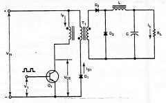
Can not unwind, dont want to rewind, but reuse old tranny. The ATX supply was based on a single switch forward converter with a 450W output , and 80+ certificate and 230V 50Hz input.

EE33 core, I think or quite close, original switching frequency about 100 kHz ( I have to check properly but in this range to get enough power out of the tranny)

Primary 60 turns , and then the reset winding 60 turns, much thinner of course. They are separated, coupled at PCB by capacitor.

Secondary is 4+4+3+3 turns, separable but connected by PCB.

Winding is outer => inner
Primary (1/2) - secondary-secondary-secondary (1/2) -secondary-secondary-reset and throw in two capacitive screen between the windings

Big Question- in a half bridge what to do with the reset winding?

Halfbridge drive with SG3525 and IR XXXX half bridge driver, no feedbuck but a current protection and soft start.

Going half bridge would increase possible power output as the flux losses goes down, and increasing the frequency gives the same V*T as the forward converter but without the reset and better output capacity.

Really, really hardcore would of course be to volt double 230V input and drive the primary in halfbridge at 230V , reusing the old mosfets, but this neccessates using 1200V gate driver IC I think... not quite there yet... I got plenty of 400V caps though...

edit: or of course going full-bridge with 230V AC in. Same voltage swing. Doule
 
Last edited:

wally7856

New member
If the reset winding is the same awg as the primary winding you could make a push pull out of it. and use both winding’s. Although with push pull you can have a flux walking problem. But if you are just playing around it might be fun to try.

Edit, oop's i see you said the reset winding is smaller awg, so full bridge may be better idea.
 

Attachments

  • forward 1 transistor sch.JPG
    forward 1 transistor sch.JPG
    33.4 KB · Views: 188
Last edited:

rikkitikki

New member
unfortunately it is way thinner, as the reset just have to carry magnetising current , not full load current.

My concernt was more to what happends if I leave it unconnected, it would develop a potential equal to the main primary voltage applied , ie 160 or 320 V depending on topology but as no current is drawn, no problem I assume or am I missing something?

Unconnected means that I would probably glue over the cores binding posts or solder these to unconnected pads.

Push pull would have been cool, a forward concerter is a half of a push pull but less prone to flux walking due to the autoreset of the core.

I would have to do some serious calculation about using a full bridge. Even if it now as forward sustaining same voltage , it sustains only half flux swing which would double in half bridge, > quadrupling core loss. and massproduced computer power supplies are not known for their overdesigned specifications... But copper loss would reduce.
 
Last edited:

wally7856

New member
Other than just insulating the free end of the reset wire i can only think of one other useful possibility. If you can get at both sides of the reset wire then disconnect it were it connects to the primary wire and reconnect the reset winding in phase with the primary. The 2 winding’s are usually wound as bifilar winding’s so they should occupy the same magnet path. Copper’s resistance goes up with temperature so hopefully the different size wires would share the current.

Single transistor forward converters take a lot of primary current and this one was set up for 340vdc operation. A full bridge would use the same voltage and have a much lower peak primary current, probably making the transformer run cooler and possibly getting more power out. An EE33 core can give a theoretical 800 watts out at 100khz. And with 60 primary turns you would have to run it around 100khz.

If the transformer primary wire was sized for its peak current you will have the extra current ability you need (plus the reset winding). As for the outputs, in a computer power supply you can not run the full rated output of each winding at the same time, the power supply will burn out. So you have extra margin built in the secondary also that you can tap with more power available on the primary.

A single transistor forward converter usually run’s a gapped core for smaller cores. I am not sure how that would affect full bridge operation.

By the way i do not know why you are worried about flux swing. 2 quadrant operation is a good thing not a bad thing. Much less winding’s and copper losses.
 

rikkitikki

New member
of course, stupid of me not to think of parallell connection of the primaries :)

As I would have to limit the power output to roughly the design power of the supply / sum of secondaries I dont se a problem of overcurrent in the secondaries either, but it is true that you can not pull max power from all of them simultaneously.
However I dont expect the copper loss to be that much anyhow , the primary is made from 0,6 mm wiring giving about 0,15 ohms, and even if the RMS current is 2A this gives < 1 W copper loss.

Secondaries are either 4 or 6 strands of same wire , I estimate about 10 mOhm resistance all of them in series (giving 14/60 * Uprimary ) and of course as max current now would be far less than when operating as designed copperloss is reduced a lot.

My concern about the flux swing is that in a full bridge flux swing is twice of the forward, quadrupling the core loss and how that would offset the lower copper losses. I guess I have to do more calculations , will be back :)

I have six broken supplies, on one I dismantled the transformer destructivly (hence the info on turns etc) aswell as splitting the core with hot water and when I checked it there was no gap.

I guess higher switch frequency removes the need for a gap as the magnetising current can be keept fairly low.

(the cause of the supplies to be scrap is bad caps on the primary, all blown)
 

wally7856

New member
“However I dont expect the copper loss to be that much anyhow , the primary is made from 0,6 mm wiring giving about 0,15 ohms, and even if the RMS current is 2A this gives < 1 W copper loss.”

What is the thickness of the reset winding.

“Secondaries are either 4 or 6 strands of same wire , I estimate about 10 mOhm resistance all of them in series (giving 14/60 * Uprimary ) and of course as max current now would be far less than when operating as designed copperloss is reduced a lot.”

Very good point, you are going for higher voltage so the high current secondary’s really help you out with copper loss.

In round numbers you could have a nice 100vdc supply. Or a +/- 50vdc supply at about 600 watts, maybe a little more. This transformer was designed to run with a fan so i think that would be the smart way to go at these higher power levels.

Thinking optimistically, 2 amp primary with .5 amp? reset = 2.5 amp x 320VDC = 800 watts. This is starting to get exciting. As an audio power supply at +/- 50vdc this could put 625 watts P-P in to 8 ohms, or 442 watts RMS. And probably up to 800 watts P-P (566W RMS) in to 4 ohms.

“My concern about the flux swing is that in a full bridge flux swing is twice of the forward, quadrupling the core loss and how that would offset the lower copper losses. I guess I have to do more calculations , will be back”

I looked this up in Pressman’s book Switching Power Supply Design 3rd ed. On page 287 he explains that major mfg disagree on the power loss from 2 quadrant to 1 quadrant operation. Pressman says a good approach is just to say 1 quadrant operation has 1/2 the losses as those shown in the flux tables. I do not see any reason to beat this to death. We are trying to squeeze every watt we can out of a core, it needs a fan and you get a free one from the ATX supply. We also have the fact that it is a small core so cooling it is more efficient than a large core.

“I have six broken supplies, on one I dismantled the transformer destructivly (hence the info on turns etc) aswell as splitting the core with hot water and when I checked it there was no gap.”

Thanks for the data on the transformer i have saved it for future use.

“I guess higher switch frequency removes the need for a gap as the magnetising current can be keept fairly low.”

The core is gapped to prevent saturation. It is not gaped if the core can sustain the flux density. The full bridge will pull this power out of the core.

“(the cause of the supplies to be scrap is bad caps on the primary, all blown)”

I belive that. I wish there was a minimum standard for caps in electronic equipment. overheated caps are a big cause of failures.
 

rikkitikki

New member
renmeasured now, main primary is 0,5 mm and reset winding is 0,2 mm in diameter. thanks for all the help.

I am not quite in how it would produce +-50V with 2*(4+3) turns on secondary, 60 on primary and then 320V swing (assuming close to 100% DC) , but yes , given that the total power loss is not to high, fan cooling is a must it should be possible to get 6-700W from it.
I go Pressmanns book aswell, and read that page but I am not quite sure about it. But again, why beat it to death when a fan solves much of the problem and copper loss is less. I guess it is worth testing some.

Yes, of course the gap is there to reduce flux density. It can also be reduced by increasing frequency (ie reducing V*sec)

BTW it is a HP PS-6361-4HFD power supply, but open it up and it is a Liteon PS-6361-4HFD power supply :)

It is really a funny supply because I can not find any of the typical control IC, it seems that is is constructed with a LM358 and a lot of discrete transistors, and it has a PS225 IC (a 4 rail monitor IC for overcurrent, over/undervoltage etc)

Only IC is the PFC controller (CM6800) and the housekeeping circuit with a TOP244 flyback transformer and circuit.
 

wally7856

New member
“renmeasured now, main primary is 0,5 mm and reset winding is 0,2 mm in diameter. thanks for all the help.”

Are the secondary’s still 0,6mm. And are these measurements on bare wire or insulated. Also if you still have the wire can you measure the length of each that would make resistance calculations very close.

“I am not quite in how it would produce +-50V with 2*(4+3) turns on secondary, 60 on primary and then 320V swing (assuming close to 100% DC) , but yes , given that the total power loss is not to high, fan cooling is a must it should be possible to get 6-700W from it."

14 turns total secondary / 60 turns primary = .23333
.23333 ratio x 320vdc hopeful primary voltage = 74.66vac on secondary’s.
74.66vac on secondary’s. x 1.414 = 105.6vdc, not counting diode voltage drop.
Now wire for 4+3- center tap -4+3, and you have +/-, 52.8vdc, not counting diode voltage drop.

“Yes, of course the gap is there to reduce flux density. It can also be reduced by increasing frequency (ie reducing V*sec).”

By flux density i was thinking about the high primary peak current in a 1 transistor forward converter. It only has 1 pulse per cycle, half of a full bridge, so the primary current is very high about 2x of bridge. This can saturate the transformer even though the average current is much less. So without a gap the transformer must be oversized so it does not saturate.

“BTW it is a HP PS-6361-4HFD power supply, but open it up and it is a Liteon PS-6361-4HFD power supply”

I read a article that said there are only 3 or 4 atx power supply makers in the world that make everyones power supply.

“It is really a funny supply because I can not find any of the typical control IC, it seems that is is constructed with a LM358 and a lot of discrete transistors, and it has a PS225 IC (a 4 rail monitor IC for overcurrent, over/undervoltage etc)

Only IC is the PFC controller (CM6800) and the housekeeping circuit with a TOP244 flyback transformer and circuit. “

Wow, good job tracing all that out.

Many people come in here with an EE33 transformer from a ATX power supply. I hope you build the full bridge circuit, do a few power tests and share the design. This would help many people.

If you want help designing it i would help.
 

farhan

New member
identify core shape

power is 450W, frequency is 100K, EE30 core are not enough, you should be select EE50 or ETD49

Hi
¨
i want to know that if i have a transformer from a SMPS.how to identify that which core shape it is as it is ETD39 or ETD59 ,is it by size of the core ,i mean the length.
 
Top