A 2-Switch Forward converter is a good choice for a lab power supply pre-regulator. You should set it up to regulate just a few volts higher than the output, then do the final output regulation with linear regulators to eliminate any switching noise between the SMPS and the final output terminals. The lower the voltage dropped across the linear regulators equals significantly less heat than a single stage linear supply. A TSFC(Two-Switch Forward Converter) is very easy to setup to use constant current output (output current limiting) since it uses current mode regulation and since the secondary rectifier is essentially a buck converter. Now, on to the problems...
1.) The TL494 is a PWM controller based on an old design. While this chip has been used in millions of different types of power supplies, I've never seen one used in a TSFC. The TL494 cannot do true current-mode control, so it is almost always driving a half-bridge supply in voltage-mode control. I have seen them used in low-voltage push-pull power supplies, such as those used in car audio sub-woofer amplifiers.
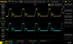
2.) As you found out, the TL494 cannot directly drive a MOSFET. The outputs of the TL494 are uncommitted transistors. They can either be configured to pull-up or pull-down, but they are single ended. This is the reason you need the 2-transistor totem-pole to drive your GDT MOSFET properly, like you showed in the
image in post #5. Even then, you should have a 1K to 2.2K resistor going to ground and connected at the junction where R1, D4, and D5 all connect together to give a good solid pull-down for when the transistor in the TL494 turns off. You can then use the output from the totem pole to drive a MOSFET gate which can be used to drive the GDT.
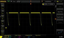
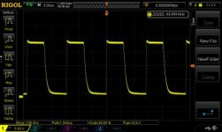
3.) You also showed another issue regarding the output of the TL494. When in single-ended mode, both outputs have the same signal and the maximum duty-cycle is over 95%. This is completely useless for a TSFC as the duty-cycle must be limited to less than 50% to ensure the power transformer can reset during its off period. You said you used a POT to adjust the DTC pin to limit the duty-cycle to <50%, but this isn't ideal. You should set the TL494 to operate in push-pull mode so the outputs are limited to <50% by default. Then you would just use one of the TL494's outputs to drive your GDT and leave the other output unconnected.
4.) Finally, I would recommend dropping the TL494 all together. While it is a simple chip to use, although it is often difficult to get right, it really isn't meant for the type of power-supply control that you need for a TSFC design. I'm sure that you could get a working supply using the TL494, but it is a poor choice for the TSFC topology and it would take a lot of effort to get it to work properly. I would recommend that you use something like the UC3844/UC3845. These are very cheap 8-pin chips. They have a single output that can directly drive a MOSFET for your GDT. They feature true current-mode control regulation and the 3844/3845 are internally limited to a 47-49% duty-cycle, both of which are ideal for a TSFC. (The UC3842/3843 go up to 98% for other types of supplies.) Examples of TSFC supplies that use the UC3844/3845 can be found all over the internet, many are proven designs. I did have application notes that show good examples of these, but I can't seem to find the files right now. If I locate them I will post them for you.
Please note, I am not an expert in SMPS design or engineering. My suggestions here are based solely upon my own experience in building power supplies and from other designs that I have studied.
-Brad
Edit: These UC384x chips can often be found in newer(since 2000) ATX computer power supplies and/or ones that are higher powered(>400W). They're sometimes even configured in the TSFC topology so if you found one it would not only give you the chip, but a good, proven example design to help you with your own.


")