I have a TDK datasheet which quotes 288W output power for their EI33 at 100kHz, 200mT based on a forward converter. They do seem to extrapolate this to silly wattages for a a forward converter on their bigger cores, so I don't know how reliable this is. Higher frequency increases the power density. If you can confirm the core material you can look up on the datasheet what the core loss would be for a given flux density, frequency and temperature and you can work out your copper losses easily enough based on just resistances (DC and AC if you account for skin and proximity effects). Transformers typically get to 100'C inside and that's fine, the core loss graph on the datasheet will show at this temperature, but various insulation will fail if it goes much higher (3M type 56 tape is specified to 130'C, their polyimide (Kapton) tapes range from 155-180'C).
Not using the voltage doubler would be more suitable for single switch forward and push-pull topologies that don't like high input voltage as they require a transistor with a voltage rating of double the input voltage plus a significant margin, which gets tricky when Vin=400V from a PFC for example. Half bridge converters suit voltage doublers quite well, but you could really do it either way. DC copper loss is I^2*R, so lower current does reduce dissipation, but your copper loss shouldn't be massive anyway. High voltage low current means half the wire cross section but double the wire length which I think means the same amount of copper, lower current but higher resistance, so it balances out.
EI cores aren't necessarily much smaller than an EE core (e.g. I have dimensions for EI core measuring 33x29mm, and an EE measuring 34x36mm). One advantage of EE cores over EI cores, although not relevant to this, is that if you want to add a gap, the gap will be in the right place in the middle of the winding rather than off to one side.
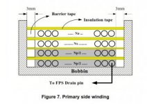
I use multiple strands of AWG31/SWG34 ECW where possible for 100kHz which should be thin enough to get past both skin and proximity effects [76/SQRT(Fs) is the skin depth in mm for copper, that would be the max radius for skin effect, but max diameter for proximity effect IIRC]. Set the total cross sectional area of copper in a winding for a current density of between 2.5-3.5A/mm2 for tightly bundled wires such as in a transformer, up to 5A/mm2 for loose wires that can cool more easily. I also have some 0.2mm thick copper foil which I use when the winding current is over roughly 5A, but it's not particularly easy to use as it's not insulated and a pain to solder. Most of my designs are under 250W and not very high current, so I get by. Litz wire would probably be better but the only source I have for it is eBay where you can't really specify your own dimensions and it's all really there for ham radio antennae. Tripple insulated wire would also be nice for small transformers but I don't have a source for it. I buy my cores and bobbins from RS, typically Epcos ETD in N87 material. I also use 3M type 56 tape or occasionally Kapton. Make sure if you're designing a transformer for mains isolation you maintain your 6mm creepage distance (make a 3mm margin bulked out with tape at the sides of a winding and have the insulation layers stick out into it) and tripple layer the insulation between primary and secondary. Basic functional isolation is usually sufficient for windings on the same side (i.e. pri vs sec)