12v-24v to 230v smps inverter

thameesha7

New member
Hi
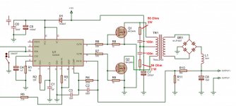
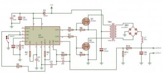
i need to make 12V-24V DC to 230V DC
inverter so i make one like this
i use Push-Pull topology and this circuit for it
http://2.bp.blogspot.com/-IGrcj4RjyY...cuit
+50kHz.png
and i use ER35 core
this is my formula Npri
http://3.bp.blogspot.com/-
vEX8Rr_RdD...alculation.png
i enter my valuve like this Vin(nom) = 24V, F
= 50000, Bmax = 1500(guass), Ae = 1.07
then my Npri = 8
and i want output like 230V 25W so i get
maximum duty cycle = 98% and my Vin(min)
= 11
so 0.98*11=10.78 and i get voltage ratio
(secondary : primary) = 250v:10.78 = 23.1
Nsec = N * Npri = 23.1*8 = 184.8
then my Nsec = 185
i get swg 26 as pri and swg 34 as sec
when i supply 12v my FET are not heat and
work fine
when i supply 24v inverter work but FET gone
heat
what is the wrong in my circuit can someone
help me please
(my english knowledge is not good sorry
about it)
 

tebci

New member
links broken!

I don't understand why you don't put the files here? just attache them!!!! R#:
 

unknown230

New member
I didnt get your design as the explanation is not that good ok whatever it might be

use current control methods for the input current then the problem will be solved
 

thameesha7

New member
I didnt get your design as the explanation is not that good ok whatever it might be

use current control methods for the input current then the problem will be solved

Dear 230
what do you mean current control methods i don't know more english can you tell me about it
 

Rogelio

New member
He means Current Limit feedback circuit for your Inverter IC. Your using Voltage Feedback to control the DC Output. Is that SG3525 IC. Can you enlarge your picture?
 

thameesha7

New member
how i make Current Limit feedback circuit i don't know how enlarge this photo i new for this forum
i didn't want 12v for this circuit can you tell me how make 24v to 230v dc-dc inverter using push pull or other low cost method with 80W output
can you help me only 24v to 230v inverter i need please help me
 

Attachments

  • circuit 50kHz.jpg
    circuit 50kHz.jpg
    21.9 KB · Views: 57

Rogelio

New member
Use Microsoft Office Picture Manager to enlarge your picture. Select your jpg file and right click to open and choose Microsoft Office Picture Manager. Then select Picture Tab, then select Resize, Click on Predermined widht X height. Then select Document Large and save it to same file name.

Post again the bigger picture and lets see what we can do. Hope we don't need Current Limit Feedback circuit.:)
 

Rogelio

New member
Place RC snubber to primary of power transformer. Switching Spike voltage might reached the Mosfet VDS 0f 60V. This is cheaper option.

If still not improve. Find Mosfet similar to IRFZ44 but with higher VDS.

What is the working voltage of C7 2200 MFD? Does it get warm also?
 

Attachments

  • SG3525 Push Pull Snubber component.JPG
    SG3525 Push Pull Snubber component.JPG
    113.7 KB · Views: 82
Last edited:

thameesha7

New member
Place RC snubber to primary of power transformer. Switching Spike voltage might reached the Mosfet VDS 0f 60V. This is cheaper option.

If still not improve. Find Mosfet similar to IRFZ44 but with higher VDS.

What is the working voltage of C7 2200 MFD? Does it get warm also?

i not use C7 is it want this?
how to find similar Mosfet to IRFZ44 with higher VDS
RC snubber is enough for this ?
this is 12v circuit but i need 24v circuit i think that i have to change full circuit
can i use 7812 for supply 12v to ic and give 24v to transformer it is work
i don't know more electronics thanks Rogelio for help me please tell me what changes i want do this circuit.
thanks
 

Rogelio

New member
If you have oscilloscope. You can see that the center tap of primary winding will have voltage spikes or electrical noise ranging 6V to 40V. You need to filter out this noise so that IRFZ44 Mosfet will not heat up. Maybe this was causing your problem. You have to filter out those noise.

You still use your IRFZ44 and install those RC snubber and place a filter capacitor with 2,000 MFD 100VDC.

SG3525 operating voltage was 8V to 35V so no need for LM7812. But you can still place LM7812 or a 12V Zener diode with series resistor. You still maintain the original circuit of the 12V Inverter circuit.
 
Last edited:

thameesha7

New member
DSC_0122.jpg

Rogelio this is my circuit i use lm7812 and RC snubber, filter capacitor 2200Uf 63V and IRF540 Mosfet
circuit is work for 12v and 24v but FET gone heat more i think i have to change Mosfet so what is the
FET i want to use for this for work low heat please help me
 

Rogelio

New member
What's the actual load and output current? Your IRF540 have a VDSS of 100V and ID=33A which was correct for your circuit. I think you need a bigger and thicker Aluminum heat sink.
 
Last edited:

thameesha7

New member
i need 230v and 80w power out as a input volatage is 24v so i think i have to re calculate my SMPS transformer again can i make this without heat sink
 

Rogelio

New member
I think you already computed primary winding of transformer into 24V and its working. You really need Heat sink to protect your Mosfet. Never saw an SMPS without heatsink.
 

thameesha7

New member
hm ok Rogelio thanks your support i need one more help
how calculate transformer wire guage for output and input Ampear please tell me it
 

Rogelio

New member
Maybe your calculated wire size was correct. But your pwm frequency was 50khz. You can not use single copper wire or 1 strand for your primary wire. It should be multiple wire. Divide wire size into 3 then twist the 3 strands and wind it again to the transformer core.
 

thameesha7

New member
i use ER35 core and pri is 26swg 8 turns single wire, sec is 34swg 117 turns single wire i have to multiple this 26swg wire am i correct
how about sec wire is it enough for sec?
can you tell me how we are select this wire swg valuve for our work i like to know about it
thanks
 
Last edited:

Rogelio

New member
Try to rewind your existing ER35 transformer using this following data.

Primary winding: 5 turns + 5 turns AWG#21X2 ( twist 2 awg#26 wire before winding )
Secondary: 60 turns AWG#22 single wire only.

Note: computed using ER35 transformer, Input 24V, Output 230V 80W, using IRF540 Mosfet Push pull and will use Bridge type rectifier.

Hope this help.
 
Top