Thanx Exflaco do you have schematic of yamaha Used?is it possible to use igbt on Detex 1.2kw with that oscillator transformer
enjoy yourself irvy
Attachments
-
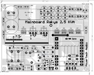
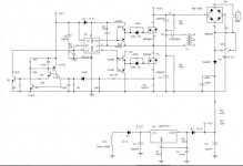 diysmps Project 1pg 5 SMPS_FULL.jpg40.7 KB · Views: 778
Thanx Exflaco do you have schematic of yamaha Used?is it possible to use igbt on Detex 1.2kw with that oscillator transformer
Irvi you can stack 2 cores etd 49 same detex schem and use igbt ,2000w easy ,or ir2153,more totem pole and igbt (yamaha schem)
Hi Exflaco
greetings do you have daughter pcb SG3525A OSCILLATOR PCB
warm regards
michelle
here are the list of igbt on hand
irg4pf50wd 4pcs
irg4pc60u 4pcs
IXDH35N60B 4pcs
HGTG18N120BN 6pcs
IXFX38N80Q2 6pcs
IXFX15N80 4 pcs
Hello people,
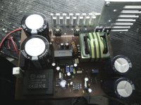
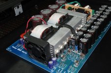
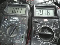
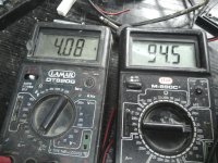
after a tons of reading posts, I decide to try my own version off Ludo SMPS. I made new PCB in Protel , and put main stuff and OC protection on main PCB. For first run I used irf740 (if they blew up, no big thing), and EE39 core from Feroxcube - 3c90. Smps worked from first power-on OK, and I got 105V at output , started with smaller load -100w bulb -ok, max. load I have was 2kW heater, when SMPS was loaded with 450w (
current from secondary was 4,8A, voltage was drop at 95V) and transformer started to buzz..
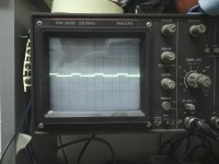
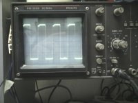
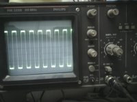
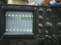
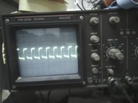
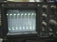
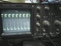
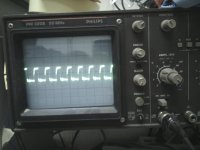
There was funny trace on my scope, was different between the two gates.. like on pictures, I changed Ir2110, but same thing... please help someone?
Please show waves across each mosfet S+D whne the smps was loaded 450W
What is the value of the series capacitor?
What is the primary number of turns?
Also show the waves across the S+G of each mosfet
regards
Hello Microsim May i know what frequency on this smps design of yours ,,can i use this calculator (ExcellentIT-En) for the following core ee55,etd40,etd59,T50 ring core
It is 12 ohms. Do you think that it is better to wound transformer with ETD49 core and see how it will be?@mikile
what is the value of the gate resistor?