1kW smps project (based on MicrosiM design)

I loaded the SMPS for about 40 minutes with 500W and here's the temperature results:

Mosfets body >> 66'C
Output Diodes body >> 73'C
Input bridge >> 78'C
Transformer cores >> 61'C

All temperatures above unit is Celsius

21.jpg 22.jpg
 
Last edited:

MicrosiM

Administrator
Staff member
I loaded the SMPS for about 40 minutes with 500W and here's the temperature results:

Mosfets body >> 66'C
Output Diodes body >> 73'C
Input bridge >> 78'C
Transformer cores >> 61'C

All temperatures above unit is Celsius

View attachment 5394 View attachment 5395


I think you have a very nice results fom first shot.

Improving the effeciency of the SMPS is another thing, also reaching above 87% of effeciency (at Full Load) is not an easy task. otherwise you go with PFC.


Good luck
 
I think you have a very nice results fom first shot.

Improving the effeciency of the SMPS is another thing, also reaching above 87% of effeciency (at Full Load) is not an easy task. otherwise you go with PFC.


Good luck

thank you

unfortunately When I want to see the maximum power of this circuit and I connect four element (about 1500W) for about 5 second, mosfets exploded and therefor now I got a dead SG3525, IR2110, 1n4148 fast diodes feeding gates of mosfets

But I will repair the damage

now I want to now how much power can I get from this SMPS?? can I go upper 1000W or not???
by the way, are these input current below normal???( if so, that with 5A fuse I can't get more than 800W)

0.15A with no load
3.9A with 540W drawn from output
6.8A with 949w drawn from output
9A with 1277W drawn from output
10.9A with 1536W drawn from output
 
I think you have a very nice results fom first shot.

Improving the effeciency of the SMPS is another thing, also reaching above 87% of effeciency (at Full Load) is not an easy task. otherwise you go with PFC.


Good luck

thank you

unfortunately When I wanted to see the maximum power of this circuit and I connect four element (about 1500W) for about 5 second, mosfets exploded and therefor now I got a dead SG3525, IR2110, 1n4148 fast diodes feeding gates of mosfets

But I will repair the damage

now I want to know how much power can I get from this SMPS?? can I go upper 1000W or not???
by the way, are these input current below normal???( if so, that with 5A fuse I can't get more than 800W)

0.15A with no load
3.9A with 540W drawn from output
6.8A with 949w drawn from output
9A with 1277W drawn from output
10.9A with 1536W drawn from output
 
Last edited:

MicrosiM

Administrator
Staff member
Fail

If you are using IRFP460 as power devices, its normal to fail at 1500W.

Your goal at the beginning was to drive an audio amplifier, and now you are pushing the SMPS beyond an audio amplifier use, I wonder why you are looking for that amount of power?

Remember, reaching that amount of power requires proper made transformer with litz wire, High quality PCB, Good PCB layout, etc...

So for an audio amplifier use, I think you are OK with your results, beside I am sure that your layout and your transformer (maybe) has the minimum safety regulations.

Good luck
 
Last edited:

vdij

Member
I got a dead SG3525, IR2110, 1n4148 fast diodes feeding gates of mosfets
Oh, congratulations, this is only the beginning, I slept the whole bucket:anonymous:. Place the GDT, the PWM controller will remain intact. Sorry for my English.
 
If you are using IRFP460 as power devices, its normal to fail at 1500W.

Your goal at the beginning was to drive an audio amplifier, and now you are pushing the SMPS beyond an audio amplifier use, I wonder why you are looking for that amount of power?

Remember, reaching that amount of power requires proper made transformer with litz wire, High quality PCB, Good PCB layout, etc...

So for an audio amplifier use, I think you are OK with your results, beside I am sure that your layout and your transformer (maybe) has the minimum safety regulations.

Good luck

I was just curious how much power can I get(because as I said in the first place I wanted to drive my 2*500W sub amplifiers and 2*200W Music amplifiers)
I thought maybe I could deliver that much power with just this SMPS


Ok I won't go beyond 1000W

you didn't mention anything about input current a fuse???

Thank you
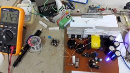
 
Last edited:

MicrosiM

Administrator
Staff member
I was just curious how much power can I get(because as I said in the first place I wanted to drive my 2*500W sub amplifiers and 2*200W Music amplifiers)
I thought maybe I could deliver that much power with just this SMPS


Ok I won't go beyond 1000W

you didn't mention anything about input current a fuse???

Thank you
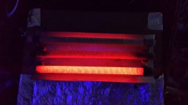

This power supply will draw more than 5A at 1500W, just do some basic calculations.
 
I replaced the dead components and now its running even better than before
With 500w load the tempreture of the mostets gets to 47"c after 1 minutes(without any heatsink or fan involved)
I think this is amazing...
I will test it with 1kw load as soon as possible, ofcourse with a larger heatsink and will report the results
 
I bring you two pictures from smps while loading 730W (50 minutes until now)
the temp of mosfets are : 100"c (becuase of the size of heatsink)
the temp of output diodes are : 60"c
the temp of input bridge is : 60"c
the temp of transformer is : about 62"C

************The input ac current is now 2.9A rms************

24.jpg 23.jpg

I placed two piece of papers between the two sides of cores to make a little gap and rapped the transformer with mylar tape to prevent any movement ( this way my output voltage is more stable and mosfets heats less and I think it's because it prevents transformer to saturates???)
 
I bring you two pictures from smps while loading 730W (50 minutes until now)

************The input ac current is now 2.9A rms************

input power without considering power factor is 696W
output power is 730W

haaaaaaaahaaaaaa

:DIt's producing power now:D:

My battery of multimeter is dying and it produces these numbers:anonymous:
I will charge the battery and repeat the measurements
Sorry for the mixed up
 

MicrosiM

Administrator
Staff member
I bring you two pictures from smps while loading 730W (50 minutes until now)
the temp of mosfets are : 100"c (becuase of the size of heatsink)
the temp of output diodes are : 60"c
the temp of input bridge is : 60"c
the temp of transformer is : about 62"C

************The input ac current is now 2.9A rms************

View attachment 5398 View attachment 5399

I placed two piece of papers between the two sides of cores to make a little gap and rapped the transformer with mylar tape to prevent any movement ( this way my output voltage is more stable and mosfets heats less and I think it's because it prevents transformer to saturates???)


Making air gap will change the inductance of you transformer, and leakage inductance also.

So that piece of paper may get you into the proper inductance @ your running Freq.

Your test result looks really nice, I am glad that you have this success rate from first time.

I advice you to make a NEW pcb layout, if you want to make this as full project


Regards

Thank you

I will definitely build the new Pcb with your help and tips and not just formyself but for everyone who likes to build this smps without worring if it works or not
And I will share the final pcb so everyone can modify it as they want
 

MicrosiM

Administrator
Staff member
I always design my pcbs with "Express pcb" program
I will post one of my design and you say that it's ok to draw this pcb in it or not

Express PCB, is good for basic PCB job, I respect that software, but for sure I recommend something like EAGLE as minimum, if you plan to share your work as standard project.

You can download it and check it out, and view some tutorials on you tube, it will make you a pro PCB designer in 2 days.


I will try to help as much as I can in your Layout.


Good luck

OK no problem at all
I will re-learn the eagle because I used it about a few years ago and since then I work with express pcb
I'll make the eagle file

but first I need to run the protection part

because I'm going to bring the protection part in the main pcb (just one pcb for this smps)


tomorrow(I'm very sleepy and here it's 4:15 am) I will test the smps with 1kw load for an hour with large heatsink and if everything goes well, I'll start with protection part

Regards
 
Top