Without the FETs installed the high-side of the IR2110 cannot operate. The FETs are required to be in-circuit so that when the low-side FET turns on it pulls the VS pin of the IR2110 low and allows the boot-strap capacitor(The cap across VB & VS pins) to charge. This capacitor provides all of the power required to drive the high-side FET during it's switching cycle. If this capacitor doesn't charge, you can't get an accurate output from the HO pin. I haven't seen the schematic for the supply you are building, but depending on the design there are a handful of different ways to test the HO output of an IR2110 without the FETs installed though.
Secondly, and again I haven't seen the schematic and a link would be more helpful here, but the MUR120 diode that you previously stated shorted out above ~130VAC. What is this diode's purpose? Is it the diode that provides the VCC charge for the boot-strap capacitor? If you're using the MUR120 as a boot-strap charge diode, then that could be the reason for it's shorting above ~120-130VAC input voltage. The MUR120 is only rated for 200VDC reverse blocking voltage and 130VAC input would give a DC-BUS voltage of ~185VDC which is pretty close to this diode's limits. Theoretically you should be able to get away with ~140VAC input voltage before your bus voltage reaches the 200VDC limit of this diode, but again, I don't know all the details and it could be receiving a higher voltage for some reason I am unaware of. The UF4007 on the other hand will handle 1000VDC and I've used them many times in the boot-strapping circuit of an IR2110. The MUR160(600VDC) works really well also. I'm just a big fan of, "Overkill is underrated..."
-Brad


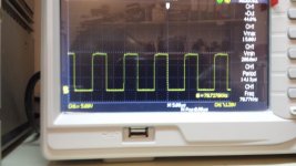
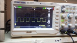
") witch is Good !
witch is Good !