You are using an out of date browser. It may not display this or other websites correctly.
You should upgrade or use an alternative browser.
You should upgrade or use an alternative browser.
1kW smps project (based on MicrosiM design)
- Thread starter ludo3232
- Start date
Jagd.Panther
New member
All right, U1 - 161B (324/2). U2 - 160V (80+80) +lose, + Efficiency
I'm not sure I understand your point. If second winding is rated for lower voltage/higher current then the wire should have more cross-section area to carry extra current (assuming we use same current density for both winding).
Last edited:
badboy_6120
Member
I'm not sure I understand your point. If second winding is rated for lower voltage/higher current then the wire should have more cross-section area to carry extra current (assuming we use same current density for both winding).
That's exactly my point
More current means more wire diameter
but now I calculated the maximum current of primary winding for 1400W output and I got about 16.7A
and output with 8A on each rail reach its maximum at 11.3A
So maybe this is right!!!!
badboy_6120
Member
put a real volt, label - AC.View attachment 5428
Our outlet voltage in normal condition is about 240V and sometimes reaches to ~260V
Jagd.Panther
New member
240v*1.41 - 0.7v*2 (to account voltage drop on rectifiers) = 337v. half bridge configuration will drive primary winding with +-337/2 = +- 168.5 v (minus voltage drop on Rds or Vcesat).That's exactly my point
More current means more wire diameter
but now I calculated the maximum current of primary winding for 1400W output and I got about 16.7A
and output with 8A on each rail reach its maximum at 11.3A
So maybe this is right!!!!
Primary current would be roughly 1400/168.5 = 8.3A. Let's account duty cycle, with 1us dead time and 70khz swithching frequency: DT = (1/70khz - 2us)/(1/70khz) = 0.86. So taking into account DT the primary current would be actually 8.3/0.86 = ~10A. Actually we should account Voltage drop on Rds@Tj=100..125degC or Vce@Tj=100..125degC at @10A (check datasheet for that, also peek the right Tj for calculation, the safer approach would be to use Tj=150+).
We
Jagd.Panther
New member
In order to get 80V+80V we must account DT, for our example running at DT=0.86 we should calculate turns ration to be 1/0.86 higher then voltage ration. For example, if we have 330V after the diode ridge rectifier and supply HB with 330V/2 - V2.5(Vce_sat ) = +-162.5V, the turn ratio should be 162.5V/(80 + 0.7V + 80 + 0.7V)/0.86 = 1.17.
So actually to get same 80v+80v = 160V on the secondaries the peak voltage on the secondaries must be ca.20% higher then on the primary winding (assuming the primary winding is driven with +-160v).
All that ^^^^ implies we have use inductors after the rectifier ridge and continuous current in the inductor. If we don't use inductors then the capacitors would be charged up to peak voltage, which is equal to turn ratio (that's , we will get +20% if we don't install inductors in this example).
Jagd.Panther
New member
To recap, if you have Half bridge supplied by ~300-340V and you need +-80V, wires for primary and secondary windings should have pretty close cross-section.
The wire diameter should be dictated by bobbin cross section area, use as thick wire as possible.
The wire diameter should be dictated by bobbin cross section area, use as thick wire as possible.
badboy_6120
Member
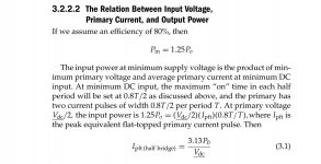
I meant the maximum current of primary in flat top of pulses
I=(Po . 3.13)/Vdc >>> I=1400x3.13/268=16.3A
Vdc= minimum rectified input voltage
I=(Po . 3.13)/Vdc >>> I=1400x3.13/268=16.3A
Vdc= minimum rectified input voltage
Jagd.Panther
New member
Where did you find this? Are you sure it fits HB?
I think the right way to calculate primary current for square wave HB, neglecting voltage drop on switches, diodes, magnetizing current, DT is:
I = Po / Efficiency / (Vdc / 2)
I think the right way to calculate primary current for square wave HB, neglecting voltage drop on switches, diodes, magnetizing current, DT is:
I = Po / Efficiency / (Vdc / 2)
badboy_6120
Member
Where did you find this? Are you sure it fits HB?
I think the right way to calculate primary current for square wave HB, neglecting voltage drop on switches, diodes, magnetizing current, DT is:
I = Po / Efficiency / (Vdc / 2)
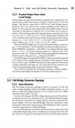
I read it from "Switching power supply design_ Third edition"
Here's the page I saw the equation in:

badboy_6120
Member
Jagd.Panther
New member
Thanks, it looks like authors assume efficiency of 80% and DutyCycle = 0.8.
badboy_6120
Member
Thanks, it looks like authors assume efficiency of 80% and DutyCycle = 0.8.
What do you think is the reason for transformer over heating?
Absolutely right.All that ^^^^ implies we have use inductors after the rectifier ridge and continuous current in the inductor.
Jagd.Panther
New member
What do you think is the reason for transformer over heating?
- test transformer under very light load. It should be barely warm. If it's not then you can either increase frequency or increase number of turns (or do both). Doing that assures you have minimal losses in ferrite. Adding more turns means you use longer wire and that translate to higher conduction losses.
- under full load transformer gets warm due to conduction losses in windings. Conduction losses depend on wire used (cross section area, skin effect) and on transformer winding (losses due to proximity effect). You have to stuff as much copper as possible and wind transformer like that: first half of primary, secondaries, second half of primary.
- don't forget about forced cooling, it permits to use higher current densities and that translates to higher output power.
Jagd.Panther
New member
We've figured out that primary winding current is close to current in secondaries. So you sohuld use thicker wire for primary winding.I red somewhere that the safe frequency for 0.25mm wire(copper) is above 100Khz
I think my winding thickness is not enough???
Primary >> 22x0.25mm
secondary >> 32x0.25mm
View attachment 5412
The left one is Secondary homemade litz: outer diameter is about 2 mm
The right one is Primary homemade litz: outer diameter is about 1.5 mm
badboy_6120
Member
We've figured out that primary winding current is close to current in secondaries. So you sohuld use thicker wire for primary winding.
Thank you for your help and answers
I will try above tips and report the results
badboy_6120
Member
I wind all the transformer winding wire in one direction but I do not remember if I start and end windings at witch pin
could this cause any problem?
could this cause any problem?
Jagd.Panther
New member
Thank you for your help and answers
I will try above tips and report the results
1st, thicker wire for primary. It's ok to have it similar in cross-section as you use for secondaries.
2nd, if the transformer is "cold" at very low loads then you can increase B, i.e. reduce number of turns & use thicker wire, that translate in lower power loss in windings but increases power loss in ferrite. the most popular option is to aim at 50/50 loss distribution
Don't forget that the higher the frequency the higher switching losses (the hotter FET's & diodes would be).
Jagd.Panther
New member
Not a problem, but you must connect all of the windings right. To do that you can use either RLC meter or an oscilloscope and some HF signal source (you need to find where "start" of every winding).I wind all the transformer winding wire in one direction but I do not remember if I start and end windings at witch pin
could this cause any problem?


