1kW smps project (based on MicrosiM design)

MicrosiM

Administrator
Staff member
Microsim For use in amplifier not would be better regulated?

Regulated SMPS has advantages also, but its more complex to make, all those you see on DIY are simple regulated SMPS units.

Also, Unregulated SMPS is easier and it does the job!

You can try making one, it will need some modifications at the circuit you have.
 

taj1989

New member
Hi Microsim!
I couldn't get 0,15 mm wire, but I bought 0,1 mm. I'd need about 900W power to my amplifier and I'd like to add an extra winding for the pre amplifier, so it would be +-90V and +-12V. How many strands do you advice for the primary and secondary winding? Thank you for your help!
 

MicrosiM

Administrator
Staff member
Use 10 thin wires, each 0.1mm for +-90VDC and primary

and 3 wires 0.1mm for +-12VDC

Twist them all, in smooth way so they are one wire.
 

Sulc

New member
Hello!

I'm planing to build SMPS. I can get ETD49 cores from our factory, Kolektor, but i'm not sure what material to choose.


Best regards
 
Hello i want to know how to test ir2110 becouse signal to ir2110 goes correctly but there`s no signal to mosfets so only choise is that ir2110 is dead. any other ideas?
 

MicrosiM

Administrator
Staff member
Hello!

I'm planing to build SMPS. I can get ETD49 cores from our factory, Kolektor, but i'm not sure what material to choose.


Best regards


If you can get 15G and 35G, since I never heard of this material. but you can ask if they are equivilant to N87 or N27 from Epcos, if Not still no problem
Get those above, or get pair of each and when testing you will find the best core.

Also its very complex to determine best core from data sheets, they are good, but last time Ludo3232 found that N27 is best for SMPS from tempreture side and power loss at 86KHz.

Get those and lets start!
 

MicrosiM

Administrator
Staff member
Hello i want to know how to test ir2110 becouse signal to ir2110 goes correctly but there`s no signal to mosfets so only choise is that ir2110 is dead. any other ideas?

Hi.

Best Idea would be an oscilloscope, I always advice every one who is making a SMPS to show there setup.

It will be difficult to test without it!
 

ravs

Member
Hi all!

i have made new revision of PCB for fixing problem of long tracks to mos and others..

It's based on same schematic of later version

I have decided to share with you the new pcb.

if anyone make copy of this pcb, keep for you, thanks.

certain values are no good readable, i fix it later and post updated files

Warning, PCB are no tested yet!!


hi ludo3232,

any updates on this project
 

taj1989

New member
Hi Microsim!

I'm almost ready with the SMPS board, now I'm starting the transformer winding. Can you check my calculations please? I made them based on a pdf file you have posted before.
so Npri= (Vnom*10^8)/(4*f*Bmax*Ae) : From the ETD datasheet Ae is 2,12 cm^2, f is 70 kHz . The core material is ASTM P5025 ( TSF50 ) power ferrite, I got it from ebay, they say that Bmax is 500 mT, but I can't find any datasheet. There are some diagrams but I couldn't find the one you have in the pdf example. So I used Bmax= 300mT and the result was 14 039, I guess that means 14 turns. For secondary I used Ns=(Np*Vs/Vp), Vp=160V, Np=14 turns and Vs is 63V (to get 90V rectified) So it gives 5,56 turns. Did I do something wrong, because these values seem too small for me.
I have another question about the winding order: I start with:
half of primary,
3 layers of tape,
half secondary for 63V (90Vdc),
2 layers of tape,
half secondary for 12V,
2 layers of tape
half sec for 12V,
2 layers of tape,
half sec for 63V,
3 layers of tape,
half primary
finally 3 layers of tape.
I hope it will fit this way, if not, can I put the two winding for 12V in one row?
For the output I bought 4700uF 100V capacitors, low esr. Are these enough? I will use the smps for an audio amlifier, that's why I bought this big capacitance.
If I succeed to finish today, tomorrow I go to the university to test the SMPS. Can you tell me some info how to test it? Is i planned, I won't solder the transformer, the the irfp-s and the output capacitors and I test the output of the IR2110 with the scope. I plan to feed the IC from DC sourceat this stage. I'll take pictures and post it. If it's OK, I solder the FET-s and the transformer. I have a 300W transformer with 56V AC output to connect to the input of the SMPS. Then I test the output voltage. Does that transformer give enough voltage to setup the smps? For the controlling IC-s I still use dc power source. Can you tell me how to set up the two trimmersfor the SG3525 and the protect board? Are the two trimmers for frequency and duty cycle?

Please help me in these questions. Thank you for your help!
 

MicrosiM

Administrator
Staff member
I'm almost ready with the SMPS board, now I'm starting the transformer winding. Can you check my calculations please? I made them based on a pdf file you have posted before.
so Npri= (Vnom*10^8)/(4*f*Bmax*Ae) : From the ETD datasheet Ae is 2,12 cm^2, f is 70 kHz . The core material is ASTM P5025 ( TSF50 ) power ferrite, I got it from ebay, they say that Bmax is 500 mT, but I can't find any datasheet. There are some diagrams but I couldn't find the one you have in the pdf example. So I used Bmax= 300mT and the result was 14 039, I guess that means 14 turns. For secondary I used Ns=(Np*Vs/Vp), Vp=160V, Np=14 turns and Vs is 63V (to get 90V rectified) So it gives 5,56 turns. Did I do something wrong, because these values seem too small for me.

Thank You!

My calculations:- based on 150V @70Khz ETD49 (Ae 2.11) Bmax 1000, Result is 25 Turns for primary, Use 24 Turns.
* For 90V output (Single output) you will need around 14.5 turns. for 90 - 0 -90 you need 14.5 -0- 14.5 turns.


Above values are 95% accurate, depends on input voltage variations. Try them. 14 Turns are too small for ETD49 @ 70Khz, its because you have use high Bmax into your calculations!


I have another question about the winding order: I start with:
half of primary,
3 layers of tape,
half secondary for 63V (90Vdc),
2 layers of tape,
half secondary for 12V,
2 layers of tape
half sec for 12V,
2 layers of tape,
half sec for 63V,
3 layers of tape,
half primary
finally 3 layers of tape.

You can do, All primary then All secondaries. This is good as a start. and simple.
use 3 Layers MINIMUM of mylar tape between primary and secondary. Also PUT isolation tape BETWEEN secondaries !

Also, winding in the way you mentions is Also 100% perfect!

I hope it will fit this way, if not, can I put the two winding for 12V in one row?

Yes

For the output I bought 4700uF 100V capacitors, low esr. Are these enough? I will use the smps for an audio amlifier, that's why I bought this big capacitance.

This is good value, but it may trigger protection circuit at first because its big, please try to locate 2x1000uf 100V in order to test the SMPS, if you cant we can deal with this.


If I succeed to finish today, tomorrow I go to the university to test the SMPS. Can you tell me some info how to test it?

1- Make AUX supply working
2- Assemble the SG3525 section and make sure its working
3- Show waves at output of SG
4- Put IR2110 chip
5- Check waves for IR2110, and show waves
6- Solder mosfets, DONT APPLY high voltage AT ALL
7- Show waves of S+G of each Mosfet, DONT FEED HIGH VOLTAGE

when you show process to step 7 , will tell how to complete, this is for your safety


Is i planned, I won't solder the transformer, the the irfp-s and the output capacitors and I test the output of the IR2110 with the scope. I plan to feed the IC from DC sourceat this stage. I'll take pictures and post it. If it's OK, I solder the FET-s and the transformer.

I have a 300W transformer with 56V AC output to connect to the input of the SMPS. Then I test the output voltage. Does that transformer give enough voltage to setup the smps?

This transformer is best for testing at safe voltage levels, NEVER connect SMPS to mains BEFORE confirming with me.


For the controlling IC-s I still use dc power source. Can you tell me how to set up the two trimmersfor the SG3525 and the protect board? Are the two trimmers for frequency and duty cycle?

please Ask uglykid about these things, he made it fully working!

Please help me in these questions. Thank you for your help!
 

taj1989

New member
Thank you Microsim for your time! Unfortunately I can't do the tests tomorrow, but next week I'll do them and follow your steps and post oscilloscope pictures.
 

MicrosiM

Administrator
Staff member
Thank you Microsim for your time! Unfortunately I can't do the tests tomorrow, but next week I'll do them and follow your steps and post oscilloscope pictures.

You are welcome.

Just when you are ready, please show waves and some pictures of SMPS. by that time, ask uglykid about more assembly of protection

Regards
 

taj1989

New member
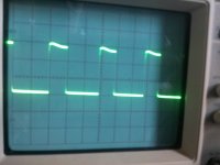
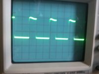
Hi! I started the tests today. The timer works perfect, and the square signals seem good. I replaced the irfp ic, because i thought that one channel is dead, but the new one didn't work either. After that i realised that i have tu turn the potmeters on the sg3525 and after than it worked. The two pictures shows the output of the sg3525 and the video shows the gate signals of the fet-s. The transformer and the fet-s aren't soldered yet. There's something wrong with the signal on the video, i don't know why, but one of the signals disappear for a time and then it comes back. Is this because the trimmers or i didn't set up the scope well?

34tdapl.jpg34repup.jpg


[video=youtube;HoSGH9OSjqc]http://www.youtube.com/watch?v=HoSGH9OSjqc&feature=plcp&context=C3c9a25cUDOEgsToPDskLv00DIaNyvMw3ZjYfaLWfB[/video]
 

MicrosiM

Administrator
Staff member
Hi! I started the tests today. The timer works perfect, and the square signals seem good. I replaced the irfp ic, because i thought that one channel is dead, but the new one didn't work either. After that i realised that i have tu turn the potmeters on the sg3525 and after than it worked. The two pictures shows the output of the sg3525 and the video shows the gate signals of the fet-s. The transformer and the fet-s aren't soldered yet. There's something wrong with the signal on the video, i don't know why, but one of the signals disappear for a time and then it comes back. Is this because the trimmers or i didn't set up the scope well?

Hello

I think your waves are OK, But you should let me know each picture related to witch test.

You have to write test name near picture, Example ( PIN 9 SG3525 and GND) picture xxx

Also your video should be closer to scope screen, please dont swap it next time !

Every thing seems OK to me, But you have to inform witch picture related to witch test

Regards ;)
 

taj1989

New member
Hi! The first picture is for pin 11 and GND, the second is pin 14 and and gnd of SG3525. The video is from the gate connection of the fet-s, but the fet-s aren't soldered yet. I'll ask tomorrow my teacher about setting up the scope, maybe i did something wrong. Sorry for swapping the video, the original is good, youtube swapped it :(
 

taj1989

New member
Hi! I soldered the two fet-s and got these signals on the output of the irfp: picture 1 is for pin1 and gnd and picture 2 is pin7 and gnd. The signal on pin 7 seems good for me, but the second one isn't ok, I think. I replaced the ic but didn't helped.


Top