You are using an out of date browser. It may not display this or other websites correctly.
You should upgrade or use an alternative browser.
You should upgrade or use an alternative browser.
300w smps need help with txfr calculation
- Thread starter sekhar
- Start date
Corvett
New member
hi guys,
i am new here i am building a 300W smps with a pfc ......... I need info on how to calculate primary , secondary turns and core size selection.....any help will be highly helpfull.....
regards
sekhar
Check here.
http://www.diysmps.com/forums/showthread.php?77-SMPS-Transformer-Primary-Turns-Calculations
Its not an easy task any way!
hi guys,
i am new here i am building a 300W smps with a pfc ......... I need info on how to calculate primary , secondary turns and core size selection.....any help will be highly helpfull.....
regards
sekhar
Sekhar
In order to get full information, let me know your Transformer Type, SMPS Topology, and all related informations, to give you help
hi,
my smps is a half bridge topology with a pfc in the front end. For beginning purpose i would like to make the smps for 300W and is intented to be used for audio amps . I want to use ETD34 as a smps txfr as it is available with me .
A few question
1.How much power can etd 34 handle at 100KHz in a bridge toplogy?????
2.I want +- 40V @ 4A or 3A is it possible for the etd34 to handle that ?????
3. flux density is a confusing thing I cant find it in cosmo ferrite hand book they mention AL(nh) value of CF196 material .
@MICROSIMS i have looked at ur smps calculations xlxs files and even the pdf .
With ur formulaes i got 41 turns in primary and 8.45 + 8.45 turns in secondary..... I it all right.....correct me if I am wrong
regards
sekhar
Etd34
@Sekhar
ETD34 Ae is 0.97 CM2
Primary voltage 150V
I assume you are using 3C90, if other let me know, thats 1200B MAX
witch gives 32 Turns for Primary. @ 100KHZ
Secondary for +- 40VDC 8.5 Turns - 8.5 Turns
When you make your first proto type, you may need to do some slight modifications +- 1 Turn.
ETD34 will give you 400W at 100KHz, ETD39 700W @100Khz. and more power for music play!
If you are going to show the results of your work here, I guarantee that you will make a good SMPS. here you will get REAL help.
Hope that helps :UP:
@microsims i have a pfc feeding the smps circuit that is I have 390V DC i/p to the smps . So the primary side will see 390/2 = 195V .
I dont know about core grade it is CF196 it is equivalent to 3c80 and the cores r from cosmo ferrite.
here is the circuit for smps will post pfc circuit later.......
regards
sekhar
I dont know about core grade it is CF196 it is equivalent to 3c80 and the cores r from cosmo ferrite.
here is the circuit for smps will post pfc circuit later.......
regards
sekhar
Attachments
@microsims
1- RSH1 is used for current sensing using lm393 which in turns, turns of the tl494 using error amp 1 in over load condition.
2- yes iam using gate drive transformer.
3- the aux for tl494 comes from the pfc section...
hey can u do quick calculation for my pfc inductor using etd34.....
regards
sekhar
1- RSH1 is used for current sensing using lm393 which in turns, turns of the tl494 using error amp 1 in over load condition.
2- yes iam using gate drive transformer.
3- the aux for tl494 comes from the pfc section...
hey can u do quick calculation for my pfc inductor using etd34.....
regards
sekhar
Pfc
I don`t advice you to sense the current using that method. it works, but some times it changes its mind to do the Job.
Gate drive transformers are Robust!, show some pictures of parts you are using, Scope waves, that will make me provide more help.
Regarding your PFC, let me know Topology, Frequency, Chip you are using. Your test results?
@microsims
1- RSH1 is used for current sensing using lm393 which in turns, turns of the tl494 using error amp 1 in over load condition.
2- yes iam using gate drive transformer.
3- the aux for tl494 comes from the pfc section...
hey can u do quick calculation for my pfc inductor using etd34.....
regards
sekhar
I don`t advice you to sense the current using that method. it works, but some times it changes its mind to do the Job.
Gate drive transformers are Robust!, show some pictures of parts you are using, Scope waves, that will make me provide more help.
Regarding your PFC, let me know Topology, Frequency, Chip you are using. Your test results?
@microsims
pfc is working in CCM topology . IC UC3854...... operating frequency 67khz....... i cant post test results right now cause the earlier boards has been confiscated by my boss ..... i am still working without his consent ....... the new single layer pcb is almost made will post pics of the board tommorow ..... this is a secret project that i am running without my bosses approval.....
regards
sekhar
Gate drive transformers are Robust
Its Kanwar who said GDT=ROBUST
PFC Calculator
You should look for PFC calculator software made specifically for UC3854, I am not sure if there is one.
Why you dont use a NEW PFC CHIP from Fairchild? as example?
All new chips comes with calculator for all values you need, including inductor.
The main issue is to find the proper core material for PFC Inductor, not the value of the inductor. :"::
Thanks
@microsims any calculations for the pfc inductor
regards
sekhar
You should look for PFC calculator software made specifically for UC3854, I am not sure if there is one.
Why you dont use a NEW PFC CHIP from Fairchild? as example?
All new chips comes with calculator for all values you need, including inductor.
The main issue is to find the proper core material for PFC Inductor, not the value of the inductor. :"::
Thanks
@microsim ......
not in KW my brother ETD49 was used in the pfc of the smps for a 500W amps . i know etd49 was a over kill but switching freq was 67khz and we had problems in 90V for full power. which i later resolved by changing some components in the FB network.....
neways my pcb r made here r the pics.............
regards
sekhar
Attachments
-
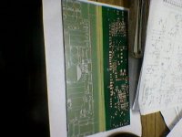 Photo-0023.jpg75.5 KB · Views: 106
Last edited: