gigabyte091
New member
Hello everybody,
after i was offline for quite a long time i decided to build flyback SMPS for my battery charger.
Here is some specs i want to achieve:
Input voltage: 230V AC (+/-10%) (about 325V DC)
Output power: 100W
Output voltage: 30V DC (adjustable from 20 to 30V if nessesery)
Output current: 3A DC (90W on main secondary, 10W on aux secondary for powering IC and cooling fan)
Fully isolated output (Feedback trought optocoupler)
short circuit protection.
Switching frequency: 70 to 75 kHz
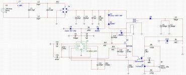
Controller IC i will use is UC3843 because its cheap and avalible in my country.
Here is schematics, its not fully completed, there is some calculation on feedback loop, frequency compensation of the TL431 as well as freq.comp. of the controller IC itself. Also at the moment im searching for optocoupler and a MOSFET as IRFP460 would be overkill for my aplication (only about 130 to 140W on primary side).
I've done transformer calculation, choose winding method.
Here is calculation:
Core type: ETD34, material: F44
F44 max. induction @ 25°C: 500 mT; @ 100°C: 400 mT
Thermal resistance: 19°C/W
-------------------------------------------------------------------------------------------------------------------------------
Power loss on transformer:
Pv=delta(T)/Rth=40/19=2.1W
-------------------------------------------------------------------------------------------------------------------------------
Primary turns: Vimin*tonmax/B*Ae=284*6.66/0.4*113= 42 turns (Where Vimin is minimum input DC voltage; tonmax is maximum on time of the switching MOSFET; B is max core induction and Ae is core area)
Main secondary turns: (Vo+Vd)*(1-tv)*Nprim/Vimin*tv= (30+2)*(1-0.5)*42/284*0.5 = 5 turns (Where Vo is output voltage; Vd is voltage drop on rectifier, tv is maximum duty cycle, Nprim is number of turns in primary)
Aux secondary turns: 3
If there is any sugestions please be free to share it with me.
after i was offline for quite a long time i decided to build flyback SMPS for my battery charger.
Here is some specs i want to achieve:
Input voltage: 230V AC (+/-10%) (about 325V DC)
Output power: 100W
Output voltage: 30V DC (adjustable from 20 to 30V if nessesery)
Output current: 3A DC (90W on main secondary, 10W on aux secondary for powering IC and cooling fan)
Fully isolated output (Feedback trought optocoupler)
short circuit protection.
Switching frequency: 70 to 75 kHz
Controller IC i will use is UC3843 because its cheap and avalible in my country.
Here is schematics, its not fully completed, there is some calculation on feedback loop, frequency compensation of the TL431 as well as freq.comp. of the controller IC itself. Also at the moment im searching for optocoupler and a MOSFET as IRFP460 would be overkill for my aplication (only about 130 to 140W on primary side).
I've done transformer calculation, choose winding method.
Here is calculation:
Core type: ETD34, material: F44
F44 max. induction @ 25°C: 500 mT; @ 100°C: 400 mT
Thermal resistance: 19°C/W
-------------------------------------------------------------------------------------------------------------------------------
Power loss on transformer:
Pv=delta(T)/Rth=40/19=2.1W
-------------------------------------------------------------------------------------------------------------------------------
Primary turns: Vimin*tonmax/B*Ae=284*6.66/0.4*113= 42 turns (Where Vimin is minimum input DC voltage; tonmax is maximum on time of the switching MOSFET; B is max core induction and Ae is core area)
Main secondary turns: (Vo+Vd)*(1-tv)*Nprim/Vimin*tv= (30+2)*(1-0.5)*42/284*0.5 = 5 turns (Where Vo is output voltage; Vd is voltage drop on rectifier, tv is maximum duty cycle, Nprim is number of turns in primary)
Aux secondary turns: 3
If there is any sugestions please be free to share it with me.
Attachments
-
 Untitled.jpg658.3 KB · Views: 488
Last edited:
