Alternative to IRG4PC50W

thimios

New member
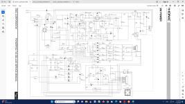
Hi guys,i have a big problem trying to repair this smps.
I hope that someone expert here can help me choosing a modern alternative to this obsolute part.
I have repair this twice using RGT40TS65DGC11 but smps burned immediately after power on.
I found that the only way to start this without shorting is using a bulb in series with the main.https://youtube.com/shorts/w6xhOAMIBLY?si=l-5ld3frK4FZnOUt
 

Attachments

  • POWER IGBT.png
    POWER IGBT.png
    290.1 KB · Views: 13

MicrosiM

Administrator
Staff member
Upload PDF file of your schematic to provide you with more help

I noticed that you are still facing challenges, and your video is showing the output voltage increasing.

I am afraid that you may have oscillation or short at the secondary side.
 

thimios

New member
I have tried to upload PDF but i got this message"The uploaded file is too large".
I have post a screenshot in post #1
Attempting to repair I have used this IGBT as alternative.https://gr.mouser.com/ProductDetail/755-RGT40TS65DGC11
Do you think that is suitable for the job?(part list recomment IRG4PC50W. which is obsolute).
 

Attachments

  • POWER IGBT.png
    POWER IGBT.png
    290.1 KB · Views: 4
  • Infineon-IRG4PC50W-DataSheet-v01_00-EN.pdf
    247.8 KB · Views: 1
  • rgt40ts65d-e-1871919.pdf
    1.1 MB · Views: 0
Last edited:

thimios

New member
Yes i have.
I have bredboard the IR2153 circuit.
I have includ all the small signal transistors around the IR2153 to understand the function of each one of them.
According to my findings
Q908 stop the oscillator when is active.
Q906 is a time delay circuit.
At startup delay the oscillator ,in compination with Q908 ,about 1".
Collector Q906 is positive and this positive voltage in Base of Q908 keep this active and IR2153 oscillator not working.
Q908 have a second role too.
This prevent the direct start after power off.
This delay is about to 15".(C913 discharge)
Q909 is an overtemperature switch.
Two thermistors,one at the main heatschink and another one in the smps transformer keep the Q909 base positive as soon as temperature is low enough.
When temperature is high base go negative and this active the 909 and this active Q908 to stop the oscillator.
Q910 is an overcurrent switch
Current sense resistors R919-920 monitor the IGPT current.
1.8 volt at point A about 3.6A is the maximum allowed current.
Here is how this repaired smps function using a bulb in series with the main.https://youtube.com/shorts/w6xhOAMIBLY?si=zKvKfnHMlXKW-NMh
Unfortunately this burned again instandly after direct connected to the main.(without bulb).
 

Attachments

  • IMG_20231110_184351.jpg
    IMG_20231110_184351.jpg
    347.5 KB · Views: 3
  • IMG_20231110_174150.jpg
    IMG_20231110_174150.jpg
    546.8 KB · Views: 7
  • IMG_20231110_174049.jpg
    IMG_20231110_174049.jpg
    392.4 KB · Views: 3
Last edited:

MicrosiM

Administrator
Staff member
The waves seem clean

Did you check the diode across pins 1 & 8 of the IR2153?

Did you check for a short circuit at the output?
 

thimios

New member
Thank you!
The waves are from the circuit that i have populate on a breadboard(this in photo ), not from the faulted smps.I'm afraid to use the scope in a non insulated circuit.
The diode between pins 1& 8 of the IR2153 (HER107) is desoldered and used in the breadboard circuit,marked in the blue circle.
I have check for short circuit at the output,all voltages are present in the output,after repair, where it was under test with a bulb in series with the main(220v) .
Please, if you find the time,can you compare the IGBT i used(RGT40TS65DGC11) with the one that is obsolute(IRG4PC50W)?
 

Attachments

  • IMG_20231110_174150.jpg
    IMG_20231110_174150.jpg
    663.5 KB · Views: 1
Last edited:
Top