Another IR2153 SMPS

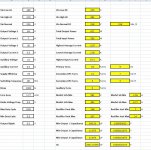
Hi i've started to start planning an IR2153 based SMPS:IR2153-Start.JPG its till in the design stage i need to complete the SMPS calculation and the scematics.
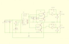
Am mostly concentrating on the issues with IR2153 before embarking on the power calculations which means

1) soft start at the poewr input rails
2) I'll use a seperate supply before using an auxiliary winding for powering the SMPS like i did for my
EI-33/TL 494 combination
3) I have ETD44 and EE42 cores around which should be enough for a 700W smps
4) Am still thinking of whether to use a core based approach or direct sense of low side mosfet for over current protection.

One question did anyone ever try to implement a soft start for the ic at the shutdown pin?
 

Bettecher

New member
One question did anyone ever try to implement a soft start for the ic at the shutdown pin?

Yes, I tried all kind of configurations before, but it didn’t works fine and I burned a lots of mosfets! Don’t try it! The best option is a simple combination of (NTC, relay ) at the ac input in order to reduce the inrush current.

Regards,

Bettecher
 
Hi Microsim and bettercher thanks for the reply i have already had a look at the yamaha EMX design and indeed it uses an NTC + relay for startup, i'll implement that.
Regarding the supply for the ic, did you try an auxiliary winding off the main smps core for powering the IR2153 or did you always use an andditional 50Hz transformer? Thanks
 

Bettecher

New member
Regarding the supply for the ic, did you try an auxiliary winding off the main smps core for powering the IR2153 or did you always use an andditional 50Hz transformer? Thanks

Zeus_threat,

At my first design I used a simple 47 K / 3w resistor from the Vbus in order to feed the IR2153, but the resistor heated up fast. Then I decided to add a auxiliary winding from the main core and increase the resistor for 150K / 2W, just for the start up.
Now is working fine! Hope it helps you.

Regards,

Bettecher
 
IC Start up

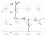
Hi bettercher thanks for the reply its exactly what am planning to implement except its going to be a series regulator that switches off when the ic starts running like this: start up.JPG

Microsim this is exactly what i implemented in my EI33 based SMPs and it works fine

There is only one issue with this circuit which is if the series pass resistors aren't powerful enough they can get very hot in case the smps does not start. There is a delayed switch off which i need to implement in the circuit i'll see if time allows but using 5W resistors everything got only warm after a long run without the SMPS starting
 

MicrosiM

Administrator
Staff member
Nice

Hi bettercher thanks for the reply its exactly what am planning to implement except its going to be a series regulator that switches off when the ic starts running like this: View attachment 2521

Microsim this is exactly what i implemented in my EI33 based SMPs and it works fine

There is only one issue with this circuit which is if the series pass resistors aren't powerful enough they can get very hot in case the smps does not start. There is a delayed switch off which i need to implement in the circuit i'll see if time allows but using 5W resistors everything got only warm after a long run without the SMPS starting


I am working around same circuit, but using 10W resistors in parallel, and also gets very hot if SMPS dont start.

They reach 160C after 30 Minutes running.

Are you able to draw 50mA current from that circuit?
 
Hi Microsim i drew about 30-40mA from the circuit. Are you planning to use it with an SG3525? The issue from what i read with TL494/SG3525 and chips of that era are that at start up all the circuits draw current which is different in motorola MC340XX series.
 
Am thinking of turning this into a ZVS Converter for experimenting. Am going through the learning of how it works. My aim is to load the half bridge output with the LC tank. It will be hard switching at the mosfet gates but soft switching at the transformer. i know Microsim's 800W design was based on this. My question is can anyone tell me if any particular magnetic core is used for the resonant inductor or is it air cored? thanks
 

MicrosiM

Administrator
Staff member
Am thinking of turning this into a ZVS Converter for experimenting. Am going through the learning of how it works. My aim is to load the half bridge output with the LC tank. It will be hard switching at the mosfet gates but soft switching at the transformer. i know Microsim's 800W design was based on this. My question is can anyone tell me if any particular magnetic core is used for the resonant inductor or is it air cored? thanks

I am not sure if you are talking about ZCS ?

My SMPS was hard switching at MOSFETS and soft at the transformer, Sine wave measured when SMPS is loaded. Is this what you mean?


Regards
 
Yes microsim exactly using IR2153 at front end and softg switching at the transformer. I have two questions:
1) did you use the leakage inductance of the transformer only + Mosfet Coss or did you use an additional core + cap for the LC tank
2) At what frequency was your smps working?

thanks
 

MicrosiM

Administrator
Staff member
Yes microsim exactly using IR2153 at front end and softg switching at the transformer. I have two questions:
1) did you use the leakage inductance of the transformer only + Mosfet Coss or did you use an additional core + cap for the LC tank
2) At what frequency was your smps working?

thanks

Yes Zeus.

I am relying at the leakage inductance of the transformer itself, without using external LC tank, this works perfect. I have seen this method used by some rare ROBUST designs.

I am currently running at 71KHz with ETD49 1.6KW, 2.1KW Peak


Hope that helps

Regards
 
Top