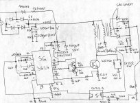
I have a problem to make forward converter - it works good with lamps load:four halogen bulbs 12V/50W and one car bulb 12V/20W connected in parallel, and I adjust the duty cycle with trimmer and everything works fine (power consumption from mains is about 0.75A).But problem is that converter should work like accu charger for car batteries 12V and load of that converter is changing through time, so I should have some regulation of voltage/current for that converter.In attachments there is schematic of my converter, way of manual regulation of duty cycle and calculations of ferrite transformer.I must say that I do not know any of specifications of ferrite core, so I calculate windings for low frequency (about 25.5kHz), because I suppose it is core older than 20 years and works on low SMPS frequency.
In fact, it seems that I have two problems.
First, current sense won't work good because it won't switch off IGBT on high current - never increase to 200mV, always stays on 185mV never get higher, but when I connect these 200mV from external supply SG3524 switches off the IGBT.
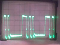
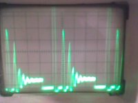
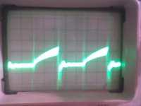
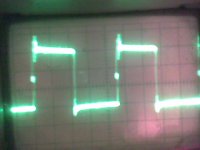
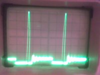
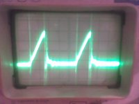
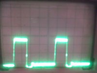
Second, I make voltage control with CNY17-3 and TL431 but when I change threshold of TL431 with trimmer connected to reference pin of TL431 suddenly converter turns off (SG3524).I thought that when I change voltage on reference pin with trimmer or change the input voltage of a converter (with manually regulated autotransformer), duty cycle should increase or decrease, in a manner to maintain constant output voltage, but it never happens.Only, when reference voltage on the other side of opto coupler comes closely to a reference of 2.5V converter is working with buzzing sound, on connected scope to the gate of IGBT, oscillogramme is not stable and after that when the reference is achieved, converter is turned off.
My question is how to make good voltage/current stabilisation and to hold egzisting configuration.Please help me!
In fact, it seems that I have two problems.
First, current sense won't work good because it won't switch off IGBT on high current - never increase to 200mV, always stays on 185mV never get higher, but when I connect these 200mV from external supply SG3524 switches off the IGBT.
Second, I make voltage control with CNY17-3 and TL431 but when I change threshold of TL431 with trimmer connected to reference pin of TL431 suddenly converter turns off (SG3524).I thought that when I change voltage on reference pin with trimmer or change the input voltage of a converter (with manually regulated autotransformer), duty cycle should increase or decrease, in a manner to maintain constant output voltage, but it never happens.Only, when reference voltage on the other side of opto coupler comes closely to a reference of 2.5V converter is working with buzzing sound, on connected scope to the gate of IGBT, oscillogramme is not stable and after that when the reference is achieved, converter is turned off.
My question is how to make good voltage/current stabilisation and to hold egzisting configuration.Please help me!
Attachments
-
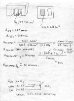 Calculations.jpg264.9 KB · Views: 176
 -
 Schematic.jpg353.7 KB · Views: 319