How To Calculate ETD Push-Pull Transformer

vindiesel

New member
Hi all

I'm totally new at smps circuits :ambivalence: ... Shift+R improves the quality of this image. Shift+A improves the quality of all images on this page.but like it alot .. now i would like to build up a 12vdc-220va power inverter using DC-DC converter then H-Bridge.

My only problem is i never wound a transformer .. i don't know how to make the calculations for the (ETD49/25/16 N87 525nH 0.5mm)----So please can i get some help here::SD ... Shift+R improves the quality of this image. Shift+A improves the quality of all images on this page.!!
 

vindiesel

New member
Thanks km-r for reply .. i know this article but have some doubts about it ... first he uses 98% duty cycly and in an issue of ELEKTOR magazine they used a 48% Duty Cycle which make sense to me .
Second he used the Vin in primary as 10.5 v or 12v and also in som ELEKTOR issue they said it should be a Peak Voltage which make tahmid's calculations may not be right
 

km-r

Still a student
a push pull smps will almost always have duty over 50% as with tahmids design... 48% duty is common with single switch flybacks so i guess thats the main difference between calculations. regarding input voltage, tahmid takes in mind that the battery (source) will drop over time whereas if the smps is powered from mains the rectified input (320vdc) will almost always be at max voltage.

the turns ratio will not hold true all the time because the feedback can compensate for it. im not an expert at smps but thats my 2c.
 

vindiesel

New member
I got it so you telling me that tahmid too used a 48% duty cycle but because it's a push-pull design it's 48% per one AC side so for both it's almost 98% am i right?
 

km-r

Still a student
yep, 98% is common max duty for push pull controllers like the TL494 and allows 2% deadtime between the push and the pull.
 

vindiesel

New member
Thanks alot KM-r You really helped me ... but one more thing i got studied the winding Calculations but my question is how to physically wind the ETD Core ... got any pictures illustrates that ?
 

km-r

Still a student
i dont know what you mean physically winding the transformer but some of the basics in winding smps transformers would be

1. always observe the winding orientation [those dots on the schematic]
2. wind the wires neat and evenly spaced fashion
3. wind wires layer-by-layer
4. put thin insulation between layers [i.e. one wrap of cellophane tape]
5. put thick insulation between the primary and secondary windings to provide isolation [at least 4 wraps of cellophane/mylar]
6. interleave windings for lower leakage inductance.

so if your primary is 40 turns and secondary around 10 turns the winding would be
first layer: 20 turns of primary
*thick insulation
second layer: 10 turns secondary
*thick insulation
third layer: the remaining 20 turns of primary
last insulation

2ho8htv.jpg
 

vindiesel

New member
first of all thanks a lot
secondly by physical winding i mean
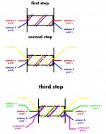
1- what the wire direction of primary and secondary do they have the same direction or against each other ?
2- do i have to sandwich the big winding layer for example i have a primary winding of 3 turns centertab the 3 turns and the secondary is 80 turns how to wind this turns ... wind the 80 turns at first then 3+3 or i must sandwich the layers i think it's not so easy for me to first time winding and sandwitch layers
3- does it matter to wind the primary or the secondary first ?
4- do i have to wind the wire in helix shape like in the picture you attached or just round circules around the bobbin?

ohh--i have too many to learn
 

km-r

Still a student
is this project of yours based on an existing design? ETD49 can handle a lot of power and mistakes can be expensive or even explosive. can you post a schematic of your project?

1. there are dots on the schematic symbol of the transformer that indicate the winding orientation. my own general rule of thumb for these dots is "this is the pin that where start winding in a clockwise direction". if these dots are not present, you can say that the primary pin is connected to the switch's drain and the secondary "dot" goes to the anode of the diode.

2. sandwiching is also called interleaving. it is always beneficial to sandwich layers of winding for lower leakage inductance but sometimes it is impractical with low turns. like on your design, 3+3 turns can just be wound as is. but the secondary can be separated like 40+40 turns. wind 40 turns, then the 3+3, then the 40 turns.
you could sandwich all you want but remember you need ample insulation between primary and secondary windings, your bobbin might not have enough space.

3. i believe this is practically more of convenience than physics. i guess other people have more insights on this.

4. not really. just wind each turn evenly.
 
Top