zeus_threat
Member
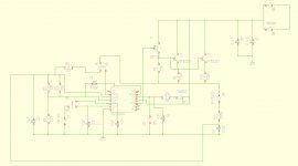
I know this is a place for SMPS but i wanted to build a transformer based bench psu. I just completed testing of this prototype:  . Current and voltage regulation are working fine i need to scope the output to see how clean it is. Currently its giving 20V 6A max continuous and >11A max in very short bursts before everything starts cooking like hell. Its enough for my purpose and it can be beefed up to give 20A continuous and 37V max.
The dc output is taken from C4
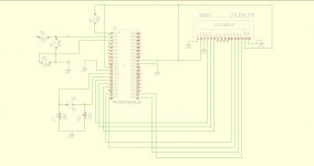
Am planning to add a pic + LCD for voltage and current monitoring as well as temperature sensor + fan.
Later on maybe digital potentiometers controlled by the pic for current and voltage control.
The project is a taken from this one and adjusted according to the components i had handy:http://sentex.ca/~mec1995/circ/ps3010/ps3010a.html
 . Current and voltage regulation are working fine i need to scope the output to see how clean it is. Currently its giving 20V 6A max continuous and >11A max in very short bursts before everything starts cooking like hell. Its enough for my purpose and it can be beefed up to give 20A continuous and 37V max.
 The dc output is taken from C4
Am planning to add a pic + LCD for voltage and current monitoring as well as temperature sensor + fan.
Later on maybe digital potentiometers controlled by the pic for current and voltage control.
The project is a taken from this one and adjusted according to the components i had handy:http://sentex.ca/~mec1995/circ/ps3010/ps3010a.html

