Q: IR2153 feedback

km-r

Still a student
hello!

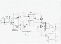
i ordered a couple of IR2153 because its a simpler implement for halfbridge vs TL494 or SG3525 but i noticed theres no error comparator/amplifier and most designs are just free oscillating/unregulated design. is there any way to implement voltage correction/feedback for this IC?

looking at the datasheet shutdown is achieved by shunting pin3(CT) to ground which i think interrupts the internal oscillator.
can it be used for feedback using an optocoupler?
wouldnt that leave one of the switches in the "ON" state?

thanks.
 

demykiko

Member
You can use it with opto like PC817 but only for shutting it down of course for safety of Two Power half-bridge switchers..
But not for feedback to correct output voltage because the IC is not a PWM IC..
When shutdown pin is activated, Its LO and HI signals really die down simultaneously..

Hope it helps!

Regards,
demykiko
 

km-r

Still a student
so it really cant have any feedback huh? im making a psu for an amplifier so i guess i'll just have to rely on the turns ratio then?

thanks for the replies! :w)
 

lynxlynx

A rumbling soft motor
I found these somewhere on internet, do not know will this work or not.
 

Attachments

  • ir2153opto.jpg
    ir2153opto.jpg
    300.2 KB · Views: 232

KX36

New member
The schematic lynxlynx posted won't work. It looks like a complete guess. It has no output inductor for duty cycle to regulate, if it does change duty cycle, it would probably change the ratio of upper to lower transistor rather than changing ontime vs offtime for the pair, saturating the transformer, it may actually just change frequency more than duty cycle. I haven't given it enough thought to think which of these it would do worst because it just wouldn't work. Essentially they've said you can turn a 555 timer into a voltage regulator by rectifying its output and sticking a transistor from the output back to the timing capacitor. Obviously that doesn't make sense.

A resonant topology looks more promising, that regulates voltage by the impedance divider formed between the resonant LC tank and the load transformed to the primary, shifting frequency adjusts the tank impedance as frequency moves away from resonance the impedance decreases. These are compex to design and you'd use an IC designed for it. They're good for high power high efficiency and generally for loads which are pretty constant. LLC and phase-shifted full bridge are the common topologies.

The 3rd option is to regulate voltage before or after the IR2153 with say a buck converter (see current-fed converters) and just use the IR2153 as an isolated turns ratio. That's probably the most sensible for a beginner, especially for lower power. Higher power requires a complex design and a lot of knowledge, you wouldn't try and bodge it out of an IC that's not designed for it.
 
Last edited:

km-r

Still a student
sorry for the late reply,

@KX36
the schematic of lynxlynx is exactly what i had in mind. so thats no-go now, thanks.
hmmm sir can you point me somewhere i can read basics about resonant converters? ive read about flyback/forward/HB/HB/PP and i think ive not read about resonant LC or ZVS

i would think the third option seems to be more feasible, hmm it may complicate things though. seems ill get more efficiency/simplicity with a 3525 or 494 but wheres the fun in that, right?
 

KX36

New member
There's plenty of info around the net on LLC and phase shifted full bridge, but as the are advanced topologies, the information is generally highly technical. They're used to meet specific needs. I don't have any specific links to hand.

A buck post-regulator using a highly integrated buck controller IC is easier than a regulated isolated topology with an optocoupler but it depends on the voltages and currents you need, whether it's a bipolar supply etc. If you did want a regulated HB, I'd recommend the 3525 over the 494 any day. Any other hard switching topology, the uc3842-uc3844 would usually be better.
 

expressel

New member
The schematic lynxlynx posted won't work. It looks like a complete guess. It has no output inductor for duty cycle to regulate, if it does change duty cycle, it would probably change the ratio of upper to lower transistor rather than changing ontime vs offtime for the pair, saturating the transformer, it may actually just change frequency more than duty cycle. I haven't given it enough thought to think which of these it would do worst because it just wouldn't work. Essentially they've said you can turn a 555 timer into a voltage regulator by rectifying its output and sticking a transistor from the output back to the timing capacitor. Obviously that doesn't make sense.
You are not right. It works and im saying that from personal experience as this is my idea too and i've already tried it.
The principle you cant get is -> powering off the IC (no lowering the freq as you thinked) when the desired voltage achieved (with zener voltage shifter+opto), then voltage will drop and the IC will turn on again. This loop holds the voltage at the desired level.

You thinked that this idea is to change the freq, lowering it, but no -> its to shutdown the IC.
 
Top