I have a couple of ideas of what might have happened. My guess would be that the VIPer100a IC is damaged and needs to be replaced and here is what I think may have killed it. I would also recommend that you replace D5 because if my idea is correct, it was probably damaged also. Maybe consider swapping in a 1A diode such as the BYT11 that you're already using in the snubber clamp, just for added reliability for the AUX supply section.
1.) I noticed that you have a jumper in place of R3(39 Ohms). The VIPer100a datasheet says that this resistor is optional but without it the IC can be subject to damage due to voltage spikes on the AUX line. These can be caused by lightning interference, but also by the sudden inrush voltage spike on the AUX line when the circuit first starts up. I don't think this is very likely to cause your failure, but I would install the resistor as a safety measure.
2.) This is what I think actually caused the damage. I think the voltage rating on your TVS diode(D3) is too high. The Drain-Source breakdown voltage of the MOSFET inside of the VIPer100a is approximately 700V. Exceeding this voltage on the drain pin can cause severe damage internally to the device. Your TVS diode is rated at 400V. Looking at the datasheet, the actual voltage can be anywhere from 380-420V at a testing current of only 1mA. As the clamping current increases, so does the clamping voltage, and at 2.8A of clamping current, the clamp voltage can rise to approximately 550V.
Your schematic has the input voltage labeled from 185-265VAC, at the lowest end of this rating(185VAC) your rectified rail voltage will be about 260VDC. During the flyback portion of the switching cycle, the drain voltage on the IC will be your rail voltage plus the clamping voltage of the TVS diode. So 260 + 400 = 660V This is getting dangerously close to the MOSFET's breakdown voltage even at the lowest of input voltage. Also, since the voltage rating of the TVS diode is specified at only 1mA, this clamping voltage will be higher than nominal. With this information, you can see that it would be very easy to exceed the breakdown voltage and destroy the IC's internal MOSFET. I'm going to take a guess here and assume that since the input is specified at 185-265VAC that the nominal input voltage is either 220 or 240VAC in your country. With an input voltage of 220VAC, your rectified rail voltage would be about 310VDC. During the flyback part of the cycle, the drain voltage would be 310 + 400 = 710V, exceeding the voltage limit. Your TVS diode needs to be specified so that during the flyback part of the cycle, the drain voltage of the VIPer IC does not exceed 700V, and we should probably factor in a little bit of error for safety. This will be calculated using your maximum input voltage of 265VAC.
265VAC gives a rectified rail voltage of approximately 375VDC.
Since the maximum drain voltage is 700V, lets leave a 50V safety margin and do the calculations at 650V.
So, with a maximum allowed drain voltage of 650V, minus the 375V of the rail, that leaves a maximum flyback clamping voltage of 275V.
With this information, that means your TVS diode should be replaced with a 1.5KE200A version. This diode has a 1mA clamping voltage of 200V with a maximum 5.5A pulse clamping voltage of 274V.
This is spot on for our calculations and even at the maximum input voltage of 265VAC, things should be safe.
I believe that due to the over voltage on the drain pin, this caused the internal MOSFET to fail as a short circuit, causing the fuse to instantly blow. I think the high voltage also damaged the internal current source that provides the VDD current during startup until the AUX supply can take over; I believe that this is what caused your AUX capacitor to fail as you mentioned.
If you replace the TVS diode(D3) with the 1.5KE200A model, replace the VIPer100a IC with a new one, and D5 with a BYT11(since you already have them), I believe your supply should function properly. Since the fuse blew, I would imagine that the transformer is perfectly fine and all of the secondary side components were isolated from the failure, so they should be fine also.
-Brad


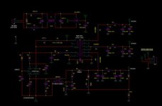 smps_sch.jpg18.8 KB · Views: 35
")


