Hi! I'm designing my first off-line SMPS. I decided to use ST's Viper IC which are cheap and easy to find, but the main reason is, ST provides free tools for designing your SMPS. On their website there's a calculator where it tells you everything, even the transformer you need (it lets you customize core and wire type and diamter, etc).
Unfortunately the part I had here was a Viper22A which isn't supported by that tool, but i found ST's older design too. It's here in case somebody wants to take a look: http://depositfiles.com/files/rm5qqxqqz
Anyway, I made a test board with the example circuit, which is this:

I found a little error there: C4 is too small (the datasheet recommends about 22uF). I changed that and the output was more stable.
The design I used is 5V 1A output.
The problem is: the SMPS isn't working.
When I turn it on (I'm using a variac, an isolation transformer, and a series 100W bulb), it goes to 5V but I can see on an analog meter that the needle is moving a little between 5 and 5.2V at about 2Hz.
If I load it with about 30 ohms, the output goes completely to zero and then back up to 5V.
If I load it with 10 ohms, the output goes to zero and the needle in my voltmeter keeps bouncing from 0 to 0.5V at about 2Hz rate.
I triple-checked everything and it all is fine, and all the values of the other components are correct in my circuit.
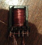
Could it be I wound my transformer incorrectly? According to the calculator, I needed to make, for an "EEL19" core, 279 turns on the primary, 88 in the auxiliary and 19 at the output. Flux density calculated is 127mT which is, I think, a conservative number (most ferrite specs i found start at over 250mT)
To build my transformer i used what i had:
279 turns of 0.15mm wire, 2 turns of 0.08mm mylar sheet, 88 t of .15, 5 turns of mylar, then 19 turns of 3 x 0.4mm (3 0.4mm paralleled). The polarity of the coils is correct and the transformer works ( I checked with a function generator and an oscilloscope)
Unfortunately the part I had here was a Viper22A which isn't supported by that tool, but i found ST's older design too. It's here in case somebody wants to take a look: http://depositfiles.com/files/rm5qqxqqz
Anyway, I made a test board with the example circuit, which is this:

I found a little error there: C4 is too small (the datasheet recommends about 22uF). I changed that and the output was more stable.
The design I used is 5V 1A output.
The problem is: the SMPS isn't working.
When I turn it on (I'm using a variac, an isolation transformer, and a series 100W bulb), it goes to 5V but I can see on an analog meter that the needle is moving a little between 5 and 5.2V at about 2Hz.
If I load it with about 30 ohms, the output goes completely to zero and then back up to 5V.
If I load it with 10 ohms, the output goes to zero and the needle in my voltmeter keeps bouncing from 0 to 0.5V at about 2Hz rate.
I triple-checked everything and it all is fine, and all the values of the other components are correct in my circuit.
Could it be I wound my transformer incorrectly? According to the calculator, I needed to make, for an "EEL19" core, 279 turns on the primary, 88 in the auxiliary and 19 at the output. Flux density calculated is 127mT which is, I think, a conservative number (most ferrite specs i found start at over 250mT)
To build my transformer i used what i had:
279 turns of 0.15mm wire, 2 turns of 0.08mm mylar sheet, 88 t of .15, 5 turns of mylar, then 19 turns of 3 x 0.4mm (3 0.4mm paralleled). The polarity of the coils is correct and the transformer works ( I checked with a function generator and an oscilloscope)


