1kW smps project (based on MicrosiM design)

meanman64

Member
Looking very good you've got my attention and I'm interested in a pcb.
View attachment 3442

I have ordered a few PCBs of my version of the SMPS design. Two sided in PCB green circa 14x12cm.
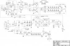
Here is the schematic and PCB: View attachment 3441

My version is for both 115VAC and 230VAC by use of a jumper.
It has an optional feedback loop with an optocoupler. You dont have to use this, but its there.
Read this thread (MultiSims messages) for what is necessary for the basic version.

The trafo is a ETD49 with N87 core. I bought them from mouser.com.
Winding info is in the schematic and in this thread. (Again: Scan for MultiSims messages)
All other components are standard and NON SMD.

It is still the first version, a prototype, but if you're interested you can buy one from me.
This will keep costs low and I will make the final version (maybe this one ?) available for purchase too.
I can also supply the trafo. But only in combination with the PCB.

Contact me for shipping costs etc.
 

PYRODCDC

New member
This SMPS includes Under voltage protection using LM311 Chip thats why its there.

There is Over current protection into this *Basic* SMPS design, The seperate board for the LM311 + The protection circuit, was to save some space, as ludo suggested!

Hello there MicrosiM and ludo,

I am new here and I was hoping to get some useful information in this forum in order to start practicing the theory that I learned. Maybe I'll do this project.

Taking into account the quote that I made, I'd like to ask you, microsim or ludo, where did you got that under-voltage and over-current protection or, in other hand if you have designed those circuits can you explain a little bit in more detail the operation of them? And how did you dimensioned the components?
Regards.
 

SR-been

New member
View attachment 3442

I have ordered a few PCBs of my version of the SMPS design. Two sided in PCB green circa 14x12cm.
Here is the schematic and PCB: View attachment 3441

My version is for both 115VAC and 230VAC by use of a jumper.
It has an optional feedback loop with an optocoupler. You dont have to use this, but its there.
Read this thread (MultiSims messages) for what is necessary for the basic version.

The trafo is a ETD49 with N87 core. I bought them from mouser.com.
Winding info is in the schematic and in this thread. (Again: Scan for MultiSims messages)
All other components are standard and NON SMD.

It is still the first version, a prototype, but if you're interested you can buy one from me.
This will keep costs low and I will make the final version (maybe this one ?) available for purchase too.
I can also supply the trafo. But only in combination with the PCB.

Contact me for shipping costs etc.
Nice work,really!

I have started to read some text from our local forum(i have mentioned this forum and thread there/put direcet links),and as much i understood there was said that the storage coil in the output between secondary rectifier diodes and capacitors provides much longer life of capacitors by decreasing currents through them(capacitors and rectifier diodes).

In this kW smps there is no that storage coil,would it be better to put it there or it wasn´t been placed here for any other reason?

Greatings!
 
Last edited:

kaip

New member
Do you mean at the secondary side of the transformer between the diodes and the capacitors/elcos ?
No reason other than "did not give too much attention to the secondary side" :)
I even thought of leaving everything out after the rectifier diodes !

But it might be good to incorporate coils in a next version.
What values do you suggest ?


Nice work,really!

I have started to read some text from our local forum(i have mentioned this forum and thread there/put direcet links),and as much i understood there was said that the storage coil in the output between secondary rectifier diodes and capacitors provides much longer life of capacitors by decreasing currents through them(capacitors and rectifier diodes).

In this kW smps there is no that storage coil,would it be better to put it there or it wasn´t been placed here for any other reason?

Greatings!
 

SR-been

New member
Sory to say this,but i am stil from those that know to reprove but don't know the answer. Here it is said really simple without going in the details:the coil from the atx pc supply should be used and to put two wind/1V . Both rails should be winded on the same torodial core. Now,if we have let's say +/-55V at output that would mean to wind 220 windings at one core. To avoid that,we should use say four of those toroides glued together and to wind quoter of windings if it was one core or 22-3 windings per rail or 54-56 in total.
I must add that this all written is how i understood it,if anyone better informed knows that i am somewhere wrong please correct me. And yes,sorry for gramar errors...
 

Pradeep

New member
Hi Friend Kaip,

In your schematic what is the value of R12 (10k or 1k) ?. there is letter "00" written nearby R1, R14, C1, C2, what does that mean ?
 

Attachments

  • smps01_sch.jpg
    smps01_sch.jpg
    194.7 KB · Views: 525
Last edited:

TANDBERGEREN

New member
Hi MicrosiM

I lost totally track here, since there is put in so many other SMPS here. A bit confusing.

Could You please put in the finished version of the schematics and for the PCB?

Also, here I would need a 230V (220V) Schematic. Possible for use to supply +/-80VDC to a good amplifier.

Thanks to both You and Ludo for both educational and fine work.
 

MicrosiM

Administrator
Staff member
Hi MicrosiM

I lost totally track here, since there is put in so many other SMPS here. A bit confusing.

Could You please put in the finished version of the schematics and for the PCB?

Also, here I would need a 230V (220V) Schematic. Possible for use to supply +/-80VDC to a good amplifier.

Thanks to both You and Ludo for both educational and fine work.


Yes, I agree with you about that.

Ludo made this SMPS for his own use, and he never shown the last file, because he worked at the design alone.

But as You can see, (Kaip) made the most corrected design as I can see.

Also you should remember that you MUST make a prototype of this SMPS. As you can see every one is making his own PCB, and there is NO official PCB release yet.

I started to think seriously to make a PCB and a well documented file for DIY, to make your own SMPS.


Let me know if you need further help

Regards
 

TANDBERGEREN

New member
Thanks.

Yes, I see I would have to make my own layout.
Would like it to fit in the enclosure I have in mind.
Aswell as giving it my own little twist.
Custom voltage, custom protection, custom monitoring.

I will look close in to this project, and see if it can be used as a basis for my own smps.
There is some issues I would like to follow up.

But again, Thanks for the inspiration and well made project.
You seems to have good knowlegde and I hope to be able to ask You whenever I am stuck.

Best regards.
 

MicrosiM

Administrator
Staff member
Thanks.

Yes, I see I would have to make my own layout.
Would like it to fit in the enclosure I have in mind.
Aswell as giving it my own little twist.
Custom voltage, custom protection, custom monitoring.

I will look close in to this project, and see if it can be used as a basis for my own smps.
There is some issues I would like to follow up.

But again, Thanks for the inspiration and well made project.
You seems to have good knowlegde and I hope to be able to ask You whenever I am stuck.

Best regards.

No Problems, I will help you any time

thanks
 

SR-been

New member
Finally i have read the whole thread...now for the next one:http://www.diysmps.com/forums/showthread.php?302-My-first-build-smps-1kw-design-by-microsim and than next one: http://www.diysmps.com/forums/showthread.php?216-800W-Half-Bridge-SMPS-for-audio-amplifier and than next one: http://www.diysmps.com/forums/showthread.php?250-IR2153-smps-with-short-circuit-protection and than next one...

I have found some answers,and also some new questions. Nice forum for these things,it should be more popular!
 

MicrosiM

Administrator
Staff member
Finally i have read the whole thread...now for the next one:http://www.diysmps.com/forums/showthread.php?302-My-first-build-smps-1kw-design-by-microsim and than next one: http://www.diysmps.com/forums/showthread.php?216-800W-Half-Bridge-SMPS-for-audio-amplifier and than next one: http://www.diysmps.com/forums/showthread.php?250-IR2153-smps-with-short-circuit-protection and than next one...

I have found some answers,and also some new questions. Nice forum for these things,it should be more popular!

SR-been,

yes there is lot of information's here, and I cannot answer every post as you can see.

I work very hard to make this place growing in the right direction.

feel free to ask

Thanks
 

MicrosiM

Administrator
Staff member
hi all is this igbt any good in smps?, can it deliver 2.5kwts in an smps? IRGB20B60P and IRGB15B60P


Hi Stewin,

These IGBTs are good for up to 700 ~ 1KW SMPS, but if you parallel two of them you may get 1.400W.

But I advice you to use something like HGTG30N60A4D as a start with your SMPS, you need something like this because the start-up current of the SMPS is huge, and you need high current IGBTs to prevent damage!!


Regards
 

SR-been

New member
SR-been,

yes there is lot of information's here, and I cannot answer every post as you can see.

I work very hard to make this place growing in the right direction.

feel free to ask

Thanks

Besides a lot of schematics and pcb´s in this thread i have also seen how much effort have you invested here and how many answer have you given. At least what i can do is to read this few threads more and to built some foundation of knowledge so i don´t need to ask you every little thing about smps. When i start my own smps i will do it with your help when you will have a time to put me to a right way and to notice me if i do anything wrong. I am really glad to find this forum and You so willing to give some answers when needed the most.

Keep on with it! :)
 

stewin

Member
Hi Stewin,

These IGBTs are good for up to 700 ~ 1KW SMPS, but if you parallel two of them you may get 1.400W.

But I advice you to use something like HGTG30N60A4D as a start with your SMPS, you need something like this because the start-up current of the SMPS is huge, and you need high current IGBTs to prevent damage!!


Regards

thanks alot sir microsim . i guess i will just stick to irfp460
 

maxente

New member
Hi everybody !
I finish my SMPS based on schematic version with SG3525 + IR2110 and protection based on ludo schematic with Lm555 and Lm393
I post some pictures
 
Last edited:
Top