You are using an out of date browser. It may not display this or other websites correctly.
You should upgrade or use an alternative browser.
You should upgrade or use an alternative browser.
1kW smps project (based on MicrosiM design)
- Thread starter ludo3232
- Start date
I tested the SMPS, with no load i have 116v, with 6A load i have 102v and with 8,22A load voltage remains at 98v
It sounds like your SMPS is working well.
I tested the SMPS, with no load i have 116v, with 6A load i have 102v and with 8,22A load voltage remains at 98v
Thats normal for UNREGULATED SMPS.
Also its good result
hi Microsim ,long time not post , i am plane to make big SMPS like +80vdc ct -80vdc*20A . i have part ,chip sg3525 & ir2110,IGBT irg4pc50u and 30n60a4d ,etd59 pc40 material ,recitifier RBV2506 for primer and FMU36 for sekunder ,capasitor primer 1800uf/200volt i have 4 pcs , email choper strands 0,10 x100 strand i have 50 meter. do you have suggest design such as how turn for primer and how freq osc and etc ,
thanks for your support,
regards,
Renotrend
thanks for your support,
regards,
Renotrend
hi Microsim ,long time not post , i am plane to make big SMPS like +80vdc ct -80vdc*20A . i have part ,chip sg3525 & ir2110,IGBT irg4pc50u and 30n60a4d ,etd59 pc40 material ,recitifier RBV2506 for primer and FMU36 for sekunder ,capasitor primer 1800uf/200volt i have 4 pcs , email choper strands 0,10 x100 strand i have 50 meter. do you have suggest design such as how turn for primer and how freq osc and etc ,
thanks for your support,
regards,
Renotrend
You can refer to _kaip_ schematics.
And 80Khz switching frequency. let me know if you will use ETD59 to give you the number of turns
regards
thanks Microsim ,i will use ETD59 PC40 material .how turns for primer ?
regards,
Renotrend
ETD59 @ 80Khz you will need:-
12 Turns for primary (half bridge SMPS)
6 Turns for 80V, that means 6 + 6 Turns for secondary
1 Turn = 13.3
All information's above are 90% accurate, due the line voltage changes, but this is exactly what you will need.
Let me know if you need more help
Hi All:
I am designing a DC to DC Converter using ETD49 but the problem is FET's are becoming too hot and cosuming over current.
Bellow the is the specification:
Primary : 2X2 turns (Copper foil)
Secondary : 100 turns (22 AWG)
Freq : 28KHz
Input Viltage : 12V
Driver IC : SG3525 (Direct drive to FET's 22ohm gate resistor)
After rectification it provides 290V DC, without load current consumption is approx 100ma but if give 200W then it takes 25A and 288V!! Even at 400W load 286V.
Looking for ward for your expert opinion to find out the problem.
Cordially,
Raj
Hi All:
I am designing a DC to DC Converter using ETD49 but the problem is FET's are becoming too hot and cosuming over current.
Bellow the is the specification:
Primary : 2X2 turns (Copper foil)
Secondary : 100 turns (22 AWG)
Freq : 28KHz
Input Viltage : 12V
Driver IC : SG3525 (Direct drive to FET's 22ohm gate resistor)
After rectification it provides 290V DC, without load current consumption is approx 100ma but if give 200W then it takes 25A and 288V!! Even at 400W load 286V.
Looking for ward for your expert opinion to find out the problem.
Cordially,
Raj
I assume your 12vdc comes from a battery being charged.
14.7vdc, 4, 28khz, 1400G, Ae 2.114 = 4.434 Turns
14.7vdc, 4, 28khz, 1500G, Ae 2.114 = 4.14 Turns
14.7vdc, 4, 28khz, 1550G, Ae 2.114 = 4.005 Turns
14.7vdc, 4, 28khz, 1600G, Ae 2.114 = 3.88 Turns
14.7vdc, 4, 28khz, 2000G, Ae 2.114 = 3.1 Turns
14.7vdc, 4, 28khz, 2100G, Ae 2.114 = 2.956 Turns
14.7vdc, 4, 28khz, 2600G, Ae 2.114 = 2.38 Turns
14.7vdc, 4, 28khz, 3000G, Ae 2.114 = 2.07 Turns
14.7vdc, 4, 28khz, 3100G, Ae 2.114 = 2.003 Turns
With 2x2 turns you are running 3100G, that is way to high.
With 3x3 turns you would have 2100G, This is high but will probably work.
With 4x4 turns you would have 1550G, This is a good safe Gauss level.
Also a 22 ohm gate resistor is probably to high also. You may not be turning the fet on fast enough. You may want to give us a schematic.
Finally the boards arrived from China.
Chinese newyear delayed them by weeks....
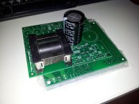
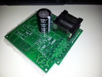
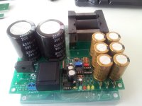
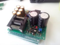
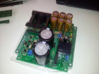
I don't have all the components yet but to give you an idea....
Found a small error with one of the blue status LED's on the output. It was the wrong way around.
Here is the latest version of the schematic (and board) with minimal components needed to make it just as Ludo and Microsim designed it here in this thread.
View attachment smps02 - Minimal.pdf
I have some extra 8 boards available for you guys.
Please send me a message if you 'd like one.
They're 20 EURO
Chinese newyear delayed them by weeks....


I don't have all the components yet but to give you an idea....
Found a small error with one of the blue status LED's on the output. It was the wrong way around.
Here is the latest version of the schematic (and board) with minimal components needed to make it just as Ludo and Microsim designed it here in this thread.
View attachment smps02 - Minimal.pdf
I have some extra 8 boards available for you guys.
Please send me a message if you 'd like one.
They're 20 EURO
I assume your 12vdc comes from a battery being charged.
14.7vdc, 4, 28khz, 1400G, Ae 2.114 = 4.434 Turns
14.7vdc, 4, 28khz, 1500G, Ae 2.114 = 4.14 Turns
14.7vdc, 4, 28khz, 1550G, Ae 2.114 = 4.005 Turns
14.7vdc, 4, 28khz, 1600G, Ae 2.114 = 3.88 Turns
14.7vdc, 4, 28khz, 2000G, Ae 2.114 = 3.1 Turns
14.7vdc, 4, 28khz, 2100G, Ae 2.114 = 2.956 Turns
14.7vdc, 4, 28khz, 2600G, Ae 2.114 = 2.38 Turns
14.7vdc, 4, 28khz, 3000G, Ae 2.114 = 2.07 Turns
14.7vdc, 4, 28khz, 3100G, Ae 2.114 = 2.003 Turns
With 2x2 turns you are running 3100G, that is way to high.
With 3x3 turns you would have 2100G, This is high but will probably work.
With 4x4 turns you would have 1550G, This is a good safe Gauss level.
Also a 22 ohm gate resistor is probably to high also. You may not be turning the fet on fast enough. You may want to give us a schematic.
Hi Wally:
Thanks a lot for your reply.
So far I know ETD49 can handle 4000G. I changed freq to 56KHz still the result is same. I checked wave shape and saw that gate driving is okay. Also used totem pole driving, same result. What is noticed is that FET's drain is not going back to 12 volt when is off. Even the gate is off, drain remains at 7 volts. That is why the loss is occurring. On the other hand other side is gets on and both drain collides somewhere at 8 volt level.
Back kick voltages to around 60v and comes down to 8 volt with some ripples. But rise to 12v is not sharp.
Any suggestion?
I have not saved any image, sorry for that. I will try to capture them next time.
Thanks
Raj
1) Post a schematic.
2) With 3x3 turns you would have 2100G, do not exceed this.
3) With no schematic my best guess is that you have your topologies mixed up. I think you have a half bridge driving your push pull and that is why you measure 7 to 8 volts on drain. Your center tap on the primary must be connected to a capacitor center tap.
Hi Wally:
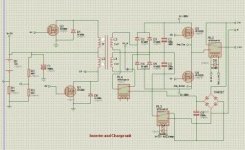
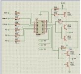
Attached is the schematics what I am trying to implement. Here you will not find SG3525 as the final will be done with a micro-controller. For testing I am using this this, just took output from SG3525 and given feedback with 680K.
I have good PWM and clean wave at gate and output voltage is stable (287V DC, 289V DC without load) even with 400W load.
I really appreciate your support.
Thanks
Raj
Hi Wally:
Attached is the schematics what I am trying to implement. Here you will not find SG3525 as the final will be done with a micro-controller. For testing I am using this this, just took output from SG3525 and given feedback with 680K.
I have good PWM and clean wave at gate and output voltage is stable (287V DC, 289V DC without load) even with 400W load.
I really appreciate your support.
Thanks
RajView attachment 3552View attachment 3553
I am glad it is working now.
