Confused regarding ferrite core power output

Silvio

Well-known member
Be careful about the switching frequency, most atx psu work at around 20 to 25Khz, so the windings are for that frequency.
If you have a lower frequency the core will get hot.

You can check what capacitor and resistor was there on the oscillator chip of the old atx psu that you dismantled the trafo from it, and you can calculate the frequency it use to work on.

Have you any means of checking the frequency your psu is working at?

Ferrite cores tend to get a little hot but not to worry much if say it will be under 100 degrees it will be ok but not more. You can add fan to keep things cool

Hope that helps
 

tibenko

New member
Documents and photos

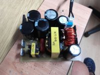
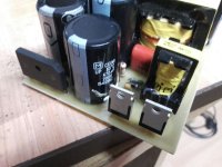
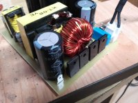
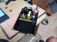
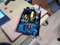
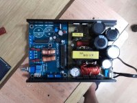
PCB is 80 x 100 mm.

I order this box from e-bay: http://www.ebay.com/itm/Black-Gold-...var=562050154465&_trksid=p2060353.m2749.l2649

And this power amplifier: http://www.ebay.com/itm/1pc-TA2022-...oard-Module-/232421943288?hash=item361d6d67f8

I will tend to use it with this SMPS. In SMPS I use 4 double diodes: http://www.ebay.com/itm/50Pcs-Mbrf1...e=STRK:MEBIDX:IT&_trksid=p2060353.m2749.l2649

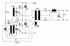
On the seconder side of ATX transformer I use windings for +-12V and I get +-27V (without regulation and with max. duty cycle on 30 kHz). As GDT I use original EE16 BDT transformer from ATX PSU with transistors. I use primer side as seconder (separate the coil, watch out for the beginning and end of the winding), and one of seconder side as primer. If you need additional explanation I will send additional photos and explanation.

TB
 

Attachments

  • shematic.GIF
    shematic.GIF
    10.5 KB · Views: 36
  • Slika 001.jpg
    Slika 001.jpg
    188.6 KB · Views: 27
  • Slika 002.jpg
    Slika 002.jpg
    184.5 KB · Views: 23
  • Slika 003.jpg
    Slika 003.jpg
    212.6 KB · Views: 20
  • Slika 004.jpg
    Slika 004.jpg
    208.7 KB · Views: 18
  • Slika 005.jpg
    Slika 005.jpg
    214.7 KB · Views: 20
  • Slika 006.jpg
    Slika 006.jpg
    223.5 KB · Views: 32
  • SMPS_ACCA.pdf
    32 KB · Views: 28
  • SMPS_ACCA_FILM.pdf
    17.2 KB · Views: 24

tibenko

New member
Thank you Silvio.

50*C isn't so much, so I can live with that (resistor 47E, 3W is very hot - about 150*C! but ... it works). I salvage this transformer a long time ago, so I don't have any chance to calculate the frequency. So...

I have another SMPS project with TL494 and IR2110. It works also, but with regulation duty cycle (3-47%) and on 50 kHz with original ATX transformer also, and without any load it's cold like an ice! But I salvage this transformer a long time ago also. This is very good project also, but this is for another topic.

TB
 

tibenko

New member
Silvio,

did you mean I must decrease number of turns per volt (on primer and seconder)? Or, I can use another ferrite core and wind it for 30 kHz.


TB
 

Silvio

Well-known member
No do not reduce the number of turns, Well I was curious at what frequency it was oscillating. As long as you have a larger frequency then the magnetic field in the trafo (B) is lower than if it was working at say 20Khz.

Your smps is self oscillating and little can be done to regulate frequency or perhaps you could play with the feedback winding on the trafo. Read well what the author (Acca I think) did and also read the tread so that you will know what others encountered.

Did you load the smps at say 200watts and see what happens? Do not forget to fit heat sink otherwise you burn your transistors and diodes

Regarding the Project it looks nice an neat, The resistor if it gets hot change it with a larger wattage. I read once a long time ago the tread of this smps and I think you can change the frequency by changing the value of the resistor I am not sure about this. One last comment do not expect more than 300 watts from this smps.

Regards Silvio
 

tibenko

New member
Hi Silvio!

I measured the duty cycle and frequency using a newer generation DMM. And I was a little surprised when I saw the result 50.1% or 50.2%, it varied. I thought it was a +-1 digit error. But it may not be so. I tried to put resistors on both MOSFETs of 1k between the gate and source terminals to speed up the MOSFET shutdown (faster the empty gate capacitor), but that did not help, just the opposite duty cycle was now permanently fixed at 50.2%.

I think the core heating problem is just a high duty cycle. Do you have any idea how to reduce the high duty cycle?

Acca is no longer active in the forum. My goal is just 200-250W. I've read the complete topic on the forum and everyone, who has made such a power supply, transformer becomes hot with no load. And it works well for everyone when powering the amplifier. Acca wrote that the amplifier with this power supply has been working for more than a year.

Resistor: I use 33E / 3W. Excessive power consumption on the resistor is a result of excessive voltage at the additional winding for the feedback on the main transformer. I tried to reduce the number of windings to 2 (as proposed by Acca in the case using original EE16 BDT from ATX), but then there is no self-oscilation, so the circuit does not work (I get only 2 volts on the seconder). I did two such power supplies and both behave almost the same.

So, I have one idea for a while, but never tested: what if I use PWM with TL494 on 60 kHz and use only half of primer? In this case I will get double voltage on seconder. I can get (in theory) 2x54V on seconder with original ATX transformer with only slight modification on that transformer and using doubled PWM frequency. When I put this data in formula for calculation number of wingdings everything is OK. I must to try this.

Thanks for your time Silvio! I really appreciate your contribution to the forum: I've learned a lot.

Regards,
TB
 

tibenko

New member
OK Silvio,

too many words. So, I was reduce frequency to 24 kHz. Duty cycle is 50,5% (worse) and core temperature 55¤C without load.

TB
 

Silvio

Well-known member
Hello Tibenko, Firstly I must say that the feedback resistor is there to limit current to the pulse trafo. I do not know what voltage you are getting at the gates. Do the zeners attached to the gates get hot during operation? If they get hot it means that the input voltage to the gates is a bit higher than necessary. This means you have to add a bit more resistance like 39 or 47 ohms instead of 33. What is keeping you from using a 5watt resistor instead of 3watts?

You did not say if the smps ran cooler or hotter with load, Did you load it or not?

Gate to source resistors are not really needed in this regard as when the pulse transformer changes phase it pulls back the charge from the fet and switches it off. This will give you a 50% duty cycle with no dead time. A light snubber across the primary will help out if any ringing is present thus not letting any delays during switching. Acca did not use any in his schematic. Do you have an oscilloscope to see what is happening?

Well for the last question regarding your Idea of running the smps at a higher frequency. This will all depend on the number of turns and also on the core material which in your case is unknown. You have to at least know the core area and from there you can work out the number of turns needed to operate it a 60Khz. I guess that the wire diameter is not suited for this frequency as the skin dept does not penetrate it all and only around half the current can pass successfully through it. This will reflect like you have a thin wire on and not enough cross sectional area to handle the current. When using high frequency the wire diameter has to be suited to the frequency of operation. The higher the frequency the thinner the wire should be, hence we use parallel wires together to cater for the needed current handling. We have a chart to refer to for this reason.

I have a video on you tube which gives some good examples how to wind transformers for smps.

Link https://www.youtube.com/watch?v=_K3ixhcTYFg

The chart I was referring to can be found in the end of this video

Link https://www.youtube.com/watch?v=TLD6hUV64YU&t

Regards Silvio
 
Top