diy 500W smps with voltage or current regulation

Silvio

Well-known member
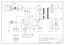
Forward converter. Your current density is too low try with 6 or 7 amps per mm^2 and use cooling fan on transformer for continuous use.

The diode forward voltage has to be taken from the data sheet of the diode. see the graph and see the voltage drop at maximum load. This could be higher than 0.6v at full load.

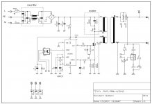
If you use half bridge topology you can use less wire on the winding and the mosfets are quite cheap to handle this power IRF740. The winding will fit better on the transformer available.

regards, Silvio
 

mojalovaa

New member
500W-smps.jpg

This is circuit diagram if can be helpful , please if you see some reason why current pwm not work correct please write me .
 

Attachments

  • 500W-smps.jpg
    500W-smps.jpg
    19.8 KB · Views: 60
  • 500W smps.jpg
    500W smps.jpg
    158.7 KB · Views: 45
Last edited:

Silvio

Well-known member
Show me some scope shots across the transformer primary to see what is happening.

Use and isolated supply on your scope as you will burn it. Use also X 100 probe
 

mojalovaa

New member
This is signal when snubber diode or FET is burn :
Up line is current and down is PWM from chip .

burn-snubber-or-FET.jpg


This is current and PWM when start devices and before burn snubber or FET , on that moment look like it work ok :

current-and-PWM-before-burn.jpg

This is signal from current sens resistor and pwm from IC with external power suply for chip , and with out 320V on the capacitors (not use AC supply on this image ).

current-and-PWM.jpg
 

Silvio

Well-known member
Picture one Top line current swing double the nominal current. You need to suppress that
Picture two Ringing at switching on again ring current double actual current
Picture Three notice the current pulse on switch off and switch on

I also noticed in the first picture that the signal from the chip is also ringing and it is reflected on the output, Try reducing the value of R3 and see what happens. compare signal before and after

Try to operate smps without feedback and compare wave forms. you can load gradually and see if waveform changes shape

If you have an un-gapped transformer core and you are using spacers remember that the spacer have to be half of the ready gapped core because the gap is now on 3 legs not only on the center leg. Try also reducing or increasing the gap and observe wave forms, I have been reading and it said that if the gap is not enough saturation of the core may occur. but be careful as the gap goes larger the inductance of the primary goes lower. Try a little at a time

In your test you have some kind of breadboard or your setup is a cobweb?
What frequency are you running at?
D3 should be UF4007 fast recovery diode
 
Last edited:

mojalovaa

New member
Hi

Today I m found one chines SMPS transformers for flyback and put it to my devices , with that transformers first time is be that smps work long time with stable voltage ,
After that I m measure inductance and measure say 5mH , then I m measure my design transformers (calculated with software ) and see that I have only 0.5mH .
Then I m change airgap on my transformers from 2 mm to 0.6 mm and connect transformers , then all so devices work , only problem then stay burn snubber , that is snuber R and C value and uF4007 diode .

Can some one help calculate correct transformer value and snubber ?
 

mojalovaa

New member
Hi

After allot time work on this smps I am decided to forward voltage because flyback is not stable , allot heating on FET an other staff.
Please can you give me more information for forward principle , can be controlled secondary voltage and similar ?
 

Silvio

Well-known member
Hi I never built a forward converter but I have built half bridge with SG3525 and IR2110 is that good for you?
 

Silvio

Well-known member
Yes I have for +/-50 to 60volts with opto coupler PC817 and TL431 if you want lower voltage you have to work out the values of the series resistor, Zener diode if necessary and and also output inductor.

The schematic I am uploading has 2 mistakes that I have seen, 1) The output is for 50-0-50 and not 80-0-80. 2) R11 on schematic should go to pin 5 of the IR2110 and not the ve- neutral. Because the Hi output is referenced to the mid point and not Ve-

Some notes on the schematic.

The author of this circuit is not using the shut down pin 10 for protection but using pin 8 (soft start) in a current fold back circuit during overload. This will minimize pulse width with the help of the current transformer sensing the output current.

The transformer secondary can be modified to suit the new voltage

You can use an auxiliary transformer and 7815 for stand by instead of the TIP50 arrangement shown on the schematic. relay coil needs 1 second delay after soft start.

View attachment smps half bridge 740 schematic b w.pdf
 

Silvio

Well-known member
No you cannot use it directly for half bridge topology. You need isolation between the high side and low side fet. I think an IR2110 is a good driver to fit after the SG3525 it can source and sink up to 2 amps of current. This will allow you to use even high power mosfets like IRFP460 etc. However for 500 watts IRF740 mosfets are enough.
 

mojalovaa

New member
Hi
After few days I'm work on new circuit diagram for my smps with SG3525 and IR2110 , if you can look and say me if you see some mistake ?
First test is be with 25 kHz on output to FET (50kHz internal oscillator ) and work is on firs look fine , on space for primary transformers coil I m put bulb 60W , all is look fine , but I m see that is not ok because on that power consuming FET is be little hot (maybe 50 celsius degree ) and all so IR2110 is be same temperature .
Then I m change frequency to 80 kHz on FET (160kHz internal ) and when I m ON smps then is firs blow IR2110 and after that boot FET and SG3525 .
Have you idea why that is happen , all so GND line from PWM module is burn .


500W-halfbridge-smps.jpg500W-halfbridge-smps.jpg
 

Silvio

Well-known member
1)Let me see your setup PCB etc
2) some general rules that you have to take when building smps. Good supply decoupling near the drive chips SG and IR.
3) Make the drive wires or traces as short as possible to the gates of fets and also away from high current paths
4) Check SG and IR output driving a couple of LEDs with 12v and 1k series resistors. Check wave form it should be nice and square on both outputs. Check also dead time. (not less than 1uS.
5) If all is well hook up remaining circuit but leave out the feed back. Hook up bulb instead of trafo and check wave form across bulb. (isolate from grid scope or supply as you will burn scope) You should see a clean square wave. If you have clean wave then proceed with hook up of trafo instead of bulb. Limit current on input with bulb.
6) Check wave form again and see if any spikes. load smps with 60watt bulb and remove bulb from input. check again for spikes and wave form.

One last comment a regulated smps should have an output inductor and also minimum load. schematic seems ok in all other things.

The IR may have burnt after the fet became short circuit and thus burning all SG and ground trace.

MY advice is to move step by step and check oscillator output and IR output before connection to rest of circuit. YOU MUST START WITH A GOOD WAVEFORM. BEWARE OF FAKE CHIPS
 
Last edited:

Silvio

Well-known member
Your setup looks ok and even the wave forms are nice. I was wondering if that wave form is of a loaded psu or off load. The suggestion of a gate source resistor is good from res_smps. This may also go to 1k in value. These will help to shut the mosfets off during the off cycle and not letting any stray inductance switch them on again. However through experience the bootstrap cap may be a bit high but knowing that your operating frequency is 25 Khz their may be enough time for it to charge up.

All I can say in my SMPS using 3525 and 2110 combination I used 22uF which works well at 60KHz. Be careful but as when at minimum duty cycle if the bootstrap cap is large (45uF) there may not be enough time for it to charge up.

If you intend to regulate the output you must use an output inductor. I experimented with mine and without it the wave shape at minimum load deforms badly and strange noises of saturation start coming out of the trafo core. However adding it things changed. You have to experiment with the value but with around 30uH is a good start. It must be just enough not to let a high voltage drop at maximum load and stable at minimum load. Headroom must be left in the output voltage to compensate for this though.

Take also care of your feedback loop that changes in voltage need to have a small delay. A small ceramic cap around 10nF across the TL431 anode and cathode. This will stabilize it.

It is best to settle first with an unregulated output and see how things behave at full load. You have to adjust the snubber values according to your findings, these tend to differ from a psu to another. The transformer construction need to have good tight coupling with minimum leakage inductance. You can connect the feedback later when you get things stable first.

One last comment if the output diodes have to handle around 20 amps (24v X 20A= 480 watts) you may need a better heatsink.
 
Last edited:

res_smps

Member
One last comment if the output diodes have to handle around 20 amps (24v X 20A= 480 watts) you may need a better heatsink.

dear silvio,

Please correct me if I am wrong, but I think the diode power dissipation is Vf(diode) x I = 0.7V x 20A = 14 Watt
 

Silvio

Well-known member
Hi I was taking a close look at the component side of the PCB and noticed that you are using the IRFP240 switching mosfets. I took a look at the data sheet and noticed that these fets are only capable of 200 volts. The voltage across these fets is around 320volts. THE VOLTAGE RATING OF THESE FETS IS NOT SUITABLE. Do not be mislead by the fact that only half the voltage is present because its not. It would be a better choice if you use IRFP460 fets instead which are rated at 500v and 20 amps

As a rule of thumb The current handling of the fets could be calculated as:-

For continuous rating the drain current of the mosfet divided by 4 (ex. 10 amp mosfet works at 2.5 -3 amps)

For 50% duty the mosfet drain current handling divided by 3 hence a 10A mosfet works at 3-4 amps

A brief calculation in your case 155v X 3amps = 465 watts

A mosfet rated for 10 to 12 amp is suitable. IRF740 will handle the load quite good. if you opt for the irfp 460 well they will be overrated and work very happily. However the IR 2110 can switch both fets with ease.
 
Last edited:
Top