DIY SMPS 1.4 Kw WITH CCM PFC

crazifunguy

New member
Hello SMPS Community

I am working on a SMPS that I would like to use for some amps I want to build. I have some schematics for a CCM PFC and a DC-DC converter. The design could meet class D and 80+ specs according simulation tests. I do however have some questions. I am well rounded in electronics but I need some design help. Here are my specs so far.

PFC Input Voltage
85V - 265V AC 50/60HZ

PFC Output Voltage
400V DC
~4A
DC-DC Converter Output Voltage
+70V 10A -70V 10A

Total Power ~1400W


Topology
CCM PFC with Half Bridge DC-DC
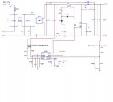
PFC.jpg

Using PowerEsim
L1 L2 & L3 are shown using 8 AWG wire. This seems too large. How do I calculate a proper wire size for these chokes and inductors??
 
Last edited:

IGBT

Switching Fanatic!
Hello SMPS Community

I am working on a SMPS that I would like to use for some amps I want to build. I have some schematics for a CCM PFC and a DC-DC converter. The design could meet class D and 80+ specs according simulation tests. I do however have some questions. I am well rounded in electronics but I need some design help. Here are my specs so far.

PFC Input Voltage
85V - 265V AC 50/60HZ

PFC Output Voltage
400V DC
~4A
DC-DC Converter Output Voltage
+70V 10A -70V 10A

Total Power ~1400W


Topology
CCM PFC with Half Bridge DC-DC

View attachment 345

Using PowerEsim
L1 L2 & L3 are shown using 8 AWG wire. This seems too large. How do I calculate a proper wire size for these chokes and inductors??


Hey,

That sounds good...

But I think 70VDC @ 10AMP for each rail, thats 2800W Output power I think, Not 1400W as you mentioned :confused:

You can use Half Bridge, Or full bridge SMPS. Search here, some examples are there.

I Can advice you to use UCC28019 From Texas Instruments, Also you will find the coil calculator for the PFC, witch will make things easier for you.


It will nice to see that project reality!
 
Last edited:

TBDz

New member
Powersim shows one inductor with 2 windings. The 2nd winding is a sense winding that is hooked up to the isense pin of the chip. Maybe there are 2 ways to configure the isense pin for the chip. Check up on the controller IC's app note.

Here is the sample datasheet. For the Infineon Controller IC
http://www.sacg.com.tw/sacweb/marcom...CE1PCS01-1.pdf
Can someone explain to me why the datasheets only use 1 inductor and the poweresim design software uses 2. I dont understand why the L4 section is present in the schematic that I posted.

I will look more into the TI stuff
 

MicrosiM

Administrator
Staff member
Core

Here is the sample datasheet. For the Infineon Controller IC
http://www.sacg.com.tw/sacweb/marcom...CE1PCS01-1.pdf
Can someone explain to me why the datasheets only use 1 inductor and the poweresim design software uses 2. I dont understand why the L4 section is present in the schematic that I posted.

I will look more into the TI stuff

crazifunguy,

I see you are unable to get help on other forums, here you go with the core calculator, core type, Number of windings you need for your PFC.


I dont know why you are sticking with that chip, you can use the suggested one by other member here, UCC. its much easier

If you need any help, just ask.
 

Attachments

  • PFC.rar
    338.5 KB · Views: 716

crazifunguy

New member
It is very ironic that you posted that file. Last week I decided to use the TI controller and basically not follow any of the PowerEsim stuff. The TI datasheet and calculator is all I need. I also have the MicroMetals calculator. So THANK YOU you have confirmed my choices.

I have questions as to the inputs of the Calculator. From this data.....what will my inputs be?
Inductance At Max Current - ?
Maximum Current - 30A
Peak Regulator Input Voltage - ?
Regulator DC Output Voltage - ?
Frequency - 65KHz


From the TI Excel Calculator:
OUTPUT:
Maximum Output Power of PFC Stage - 1600W
Output Voltage 390V
Maximum Output Current of PFC Stage - 4.103A

INPUT:
Minimum Input Voltage from AC Line - 85V
Maximum Input Voltage from AC Line - 265V

BOOST INDUCTOR DESIGN
Maximum Inductor Peak Current - 32.15A
Minimum Boost Inductor Value - .257mH
Actual Boost Inductor Value Used - 1.25mH
Actual Maximum Inductor Peak Current - 29.828A
 

MicrosiM

Administrator
Staff member
It is very ironic that you posted that file. Last week I decided to use the TI controller and basically not follow any of the PowerEsim stuff. The TI datasheet and calculator is all I need. I also have the MicroMetals calculator. So THANK YOU you have confirmed my choices.

I have questions as to the inputs of the Calculator. From this data.....what will my inputs be?

Inductance At Max Current - ? witch is inductance your TI will give after calculations
Maximum Current - 30A, current you need at 90VAC
Peak Regulator Input Voltage - ? , witch is 90VAC I think minimum
Regulator DC Output Voltage - ? witch is 385VDC in my case
Frequency - 65KHz , your frequency


From the TI Excel Calculator:
OUTPUT:
Maximum Output Power of PFC Stage - 1600W
Output Voltage 390V
Maximum Output Current of PFC Stage - 4.103A

INPUT:
Minimum Input Voltage from AC Line - 85V
Maximum Input Voltage from AC Line - 265V

BOOST INDUCTOR DESIGN
Maximum Inductor Peak Current - 32.15A
Minimum Boost Inductor Value - .257mH
Actual Boost Inductor Value Used - 1.25mH -----------> where did you get this?
Actual Maximum Inductor Peak Current - 29.828A


Please see above answers in RED. and I am ready for help
 

ravs

Member
hi crazifunguy,

check this stuff

regards

ravs


be a vegeterian......
 

Attachments

  • E876C9DBd01.pdf
    288.2 KB · Views: 385
  • MC34262.PDF
    265.3 KB · Views: 326
  • Circuits for power factor correction with regards to mains filtering.PDF
    158.2 KB · Views: 439
  • POWER FACTOR CORRECTION INDUCTOR DESIGN FOR SWITCHED MODE POWER ....PDF
    827.9 KB · Views: 575

crazifunguy

New member
I think something is wrong with the Micro Metals Calculator I keep getting excessive temp warnings or it says to use 0000 AWG wire.....Something is not right
 

crazifunguy

New member
I found 1 problem I was entering milihenries insted of micro into the calculator. Using 1250 in the box I get some results but I am not happy with them.
232 turns of 8 AWG wire on a 5 OD 3 ID core. Having to use something this large is not al all appealing to me. I would rather just use a large torid transformer and quit while I am ahead.

Why does a 1000W computer power supply use a PFC inductor the size of a quarter and for 1600W mine needs to be 5 inches with 8AWG wire??
 

crazifunguy

New member
I did some further testing and it seems that my inductors are too large. I needed a lower value for the inductor in henries. If I increase the ripple factor in the input capacitor to 40% or greater I seem to get decent results. I dont know the effect that this would have on the PFC or the output power quality but I am guessing that it is not a good thing. In the excel file under the INPUT CAPACITOR section this value can be changed.

I also came across this:
http://www.2dix.com/pdf-2011/inductor-ripple-current-pdf.php
The first 2 documents explain using an Interleaved PFC configuration for higher power and lower ripple with smaller inductors. Is this maybe a better route than higher capacitor ripple?
ALSO SEE THIS:
http://focus.ti.com/download/trng/docs/seminar/Topic5MO.pdf
 

MicrosiM

Administrator
Staff member
Calculator

Ok,

I tried those formulas and they give accurate results.

I ran the formula on windowsXP, dont know your OS.

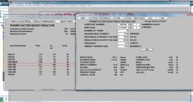
See snap below for 1350W PFC calculation.

It gave me: T-200 core T200-18B, with is 5CM Outer Diameter, its normal for that power.

Also you can ask the software to make strands of the wire to make winding easy, while it gave # 10 AWG. i can ask it to use 10 strands of # 22 AWG

PFC_Snap.jpg

Hope this helps
 

TBDz

New member
Ok,

I tried those formulas and they give accurate results.

I ran the formula on windowsXP, dont know your OS.

See snap below for 1350W PFC calculation.

It gave me: T-200 core T200-18B, with is 5CM Outer Diameter, its normal for that power.

Also you can ask the software to make strands of the wire to make winding easy, while it gave # 10 AWG. i can ask it to use 10 strands of # 22 AWG

View attachment 391

Hope this helps

MicroSim,

Thank you for showing the screen shot.

I see that the maximum current was entered as 15A. I assume that it was calculated by 1350W /90VAC = 15A. This is only the RMS current, not the absolute peak current. The peak current would be sqrt(2) * 15

In addition, I do think that the peak inductor current is 15A * 1.41 + (peak-peak ripple current / 2). The ripple current is calculated based on the inductance at full load. Based on the entered value of 200uH, the p-p current is about 4.27A so the maximum inductor current = 23.285A.

If you use this current to evaluate the inductor size again, it will show 2.5" - 3" toroid. Hope this helps.
 

TBDz

New member
MicroSim,

Thank you for showing the screen shot.

I see that the maximum current was entered as 15A. I assume that it was calculated by 1350W /90VAC = 15A. This is only the RMS current, not the absolute peak current. The peak current would be sqrt(2) * 15

In addition, I do think that the peak inductor current is 15A * 1.41 + (peak-peak ripple current / 2). The ripple current is calculated based on the inductance at full load. Based on the entered value of 200uH, the p-p current is about 4.27A so the maximum inductor current = 23.285A.

If you use this current to evaluate the inductor size again, it will show 2.5" - 3" toroid. Hope this helps.


I wanted to update after posting but I have passed the "5 minute" limitation so I must post it as a seperate post. The values shown in the poast supercede the values in the previous post.

MicroSim,

Thank you for showing the screen shot.

I see that the maximum current was entered as 15A. I assume that it was calculated by 1350W /90VAC = 15A. This is only the RMS current, not the absolute peak current. The peak current would be sqrt(2) * 15

In addition, I do think that the peak inductor current is 15A * 1.41 + (peak-peak ripple current / 2). The ripple current is calculated based on the inductance at full load. Based on the entered value of 200uH, the p-p current is about 6.69A so the maximum inductor current = 24.29A.

In addition, assuming 92% efficiency, you would estimate the peak current to be 24.29/.92 = 26.4A

This value is quite a departure from the 15A entered originally and will yield a larger inductor size.

If you use this current to evaluate the inductor size again, it will show 2.5" - 3" toroid. Hope this helps.
 

crazifunguy

New member
I agree with that. I also noticed the use of 15A. Here is what I get for 1350W using the TI design sheet.
SPECS
1350W
AC Input Voltage 85-265Vac
DC Output Voltage 390Vdc
*****ALL OTHER VALUES UNCHANGED*****

RESULTS:
Maximum Peak AC Line Current - 25A
Minimum Boost Inductor Value - .304mH (Mili Henries) - 304uH (Micro Henries)

This gives the same larger results that I was having issues with before. Thick gauges of wire and bigger cores. So I am thinking that for powers of this level I need to look into different types of PFC vs the Traditional Boost PFC.
 

Kanwar

Member
MicroSim,

Thank you for showing the screen shot.

I see that the maximum current was entered as 15A. I assume that it was calculated by 1350W /90VAC = 15A. This is only the RMS current, not the absolute peak current. The peak current would be sqrt(2) * 15

In addition, I do think that the peak inductor current is 15A * 1.41 + (peak-peak ripple current / 2). The ripple current is calculated based on the inductance at full load. Based on the entered value of 200uH, the p-p current is about 4.27A so the maximum inductor current = 23.285A.

If you use this current to evaluate the inductor size again, it will show 2.5" - 3" toroid. Hope this helps.

The Total current must include Peak Line current + HF Ripple Current and then one can evaluate core at required minimum inductance.
 

TBDz

New member
I agree with that. I also noticed the use of 15A. Here is what I get for 1350W using the TI design sheet.
SPECS
1350W
AC Input Voltage 85-265Vac
DC Output Voltage 390Vdc
*****ALL OTHER VALUES UNCHANGED*****

RESULTS:
Maximum Peak AC Line Current - 25A
Minimum Boost Inductor Value - .304mH (Mili Henries) - 304uH (Micro Henries)

This gives the same larger results that I was having issues with before. Thick gauges of wire and bigger cores. So I am thinking that for powers of this level I need to look into different types of PFC vs the Traditional Boost PFC.


Keep in mind that if increasing the switching frequency is an option for the chipset, increasing it to 100kHz from 65kHz will make the magnetics smaller.
 

MicrosiM

Administrator
Staff member
100k

Keep in mind that if increasing the switching frequency is an option for the chipset, increasing it to 100kHz from 65kHz will make the magnetics smaller.


I am running my 1200W PFC @ 100KHZ frequency, thats why I am using 5CM OD toroidal core for PFC coil. 2.2MM wire thickness.

Will post some results when I complete it.
 
Top