DIY SMPS 1.4 Kw WITH CCM PFC

crazifunguy

New member
It seems that no matter what I try 30A requires a massive inductor even with 500Khz. I am gonna explore new ideas that use multiple inductors. I am still thinking that this type of power supply at this power level is just not ideal size or cost wise.
 

MicrosiM

Administrator
Staff member
It seems that no matter what I try 30A requires a massive inductor even with 500Khz. I am gonna explore new ideas that use multiple inductors. I am still thinking that this type of power supply at this power level is just not ideal size or cost wise.

Show me snap shot of your screen, with values, lets see whats going on your side.

A 1200W SMPS with PFC, is not an easy goal!


Dont Give Up..

Thanks
 

TBDz

New member
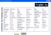
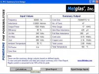
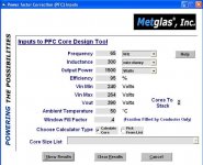
Here are the Inputs - Outputs - Results Using the TI Calculator UCC28019
View attachment 403View attachment 404View attachment 405

Is there a way to change the switching frequency of UCC28019? I know that the spreadsheet is set to calculate at 65kHz. Microsim is correct as 196 vs 300uH is significant. If the switching frequency of UCC28019 can be changed to 100kHz, the required inductance value at 30% ripple will be lower, therefore yielding a smaller inductor. The peak current of the inductor is not going to change much by increasing frequency but the decrease in required inductance is what will give you a smaller inductor.
 

ravs

Member
hi crazyfunguy,

see if it helps

starting from left

ravs

be a vegeterian....
 

Attachments

  • 3.jpg
    3.jpg
    39.5 KB · Views: 48
  • 2.jpg
    2.jpg
    43.7 KB · Views: 30
  • 1.jpg
    1.jpg
    30.1 KB · Views: 30

MicrosiM

Administrator
Staff member
The frequency is fixed with that controller IC :(

Is it safe to use just the RMS current for the inductor design?


Calculate on 17 Amps, Even 15 AMPS, using that PFC for SMPS *Audio* applications wont be a problem

I dont think there will be a problem *in prototypes*. use 17 AMPS. RMS Current is OK, I used RMS, Will show results when other parts arrives.

If you have access to those cores, get T200, T250, T300. And you will see how things will go, I dont Expect *for my self* to succeed in PFC from the first time.

Just give it a try..
 

Sierra

Valve Lover!
Mains Fuse

Let me clear one thing for all.

Mains fuse for such Power supply with PFC should be 10Amps, I never saw any smps with PFC uses 23Amps mains fuse.

If we are going to use PEAK current as refrence, then a party with 4000W power amplifiers will need more than 80AMP running at 110VAC.

I dont think this is true.
 

crazifunguy

New member
I agree with that. I am going to just prototype a design using the worst case current rounded. 85V 1400W.....Approx 15A. Once I have something to play with I can test it and see if it can handle the current draw.....If it fails I can always rebuild it. 15A sounds like a good starting point. CHEER.... Happy New Year...
 

MicrosiM

Administrator
Staff member
Pfc

I agree with that. I am going to just prototype a design using the worst case current rounded. 85V 1400W.....Approx 15A. Once I have something to play with I can test it and see if it can handle the current draw.....If it fails I can always rebuild it. 15A sounds like a good starting point. CHEER.... Happy New Year...


While you are at diysmps, you will not fail!

Do what I told you, I am telling you true results, Unless you will use this PFC for constant supply, other things will apply.
 

CobraNet

Member
Hello SMPS Community

I am working on a SMPS that I would like to use for some amps I want to build. I have some schematics for a CCM PFC and a DC-DC converter. The design could meet class D and 80+ specs according simulation tests. I do however have some questions. I am well rounded in electronics but I need some design help. Here are my specs so far.

PFC Input Voltage
85V - 265V AC 50/60HZ

PFC Output Voltage
400V DC
~4A
DC-DC Converter Output Voltage
+70V 10A -70V 10A

Total Power ~1400W


Topology
CCM PFC with Half Bridge DC-DC

View attachment 345

Using PowerEsim
L1 L2 & L3 are shown using 8 AWG wire. This seems too large. How do I calculate a proper wire size for these chokes and inductors??


You got any results?

Have you calculated values for that chip using calculator?

I would appreciate if you show me your progress

Thank you
 

crazifunguy

New member
I am back....I have been burdoned with too many things keeping me busy. I am going to continue to work on this design until completion...more to come!!
 
Top