I am back....I have been burdoned with too many things keeping me busy. I am going to continue to work on this design until completion...more to come!!
Welcome Back!
I am back....I have been burdoned with too many things keeping me busy. I am going to continue to work on this design until completion...more to come!!
Hello! I'm kind of late player here, but what the hey.
I'm also supposed to make a 2.2kW PFC. The highest rated output I've found so far is 1700W by MicrosiM. I'm hoping some of you guys could shed some light on this as well. I've already posted this on his thread about the 1kW PFC, so I'm not sure if this is legal. Just inform me and I'll stop. Or you can direct me to a helpful thread. Hehe. Anyway, here it is:
I need to design a 2.2kW PFC using the UCC28019 with the following specs:
Input Voltage: 230VAC, 60Hz
Output: 385V, 5.7A
I'm having trouble getting past the 1kW output. Mosfet keeps blowing up. I'm thinking I need to change the inductor. I'm currently using the ETD-59 ferrite core with no gap, which means about 9 turns. I'm getting the required 0.43mH (according to the component calculator from TI) but the inductor current (which I think is supposed to be a regular triangular waveform from upclose) distorts when output current gets higher than 500mA (that's about 200W). I'm getting a relatively stable 385V output though. Can any of you please help? Thank you very much. =)
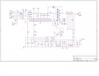
Post your schematic and transformer specs.
I have not studied boost converters so i can not give you any practical advice,
")
PFC boost converters can be used in any power level, provided you do the required things correctly.