Drive signal issues with half bridge

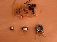
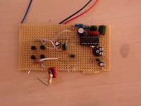
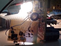
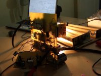
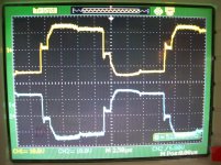
Hi I am trying to build the following SMPS, half bride based on TL494 and with isolated gate drive. Its targetted for ~150W operation +-35V OP: TL494 SMPS.jpg .Please NOTE: the gate turn off transisors are 2SA733 in reality i used those bc just for drawing . I have steps on my gate drive waveforms: pic.jpg and i have the following waveform from a current sense transformer wired in series with my main transformer : pic2.jpg.

The circuit is set to oscillate at 50KHz.

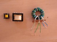
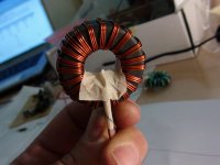
The gate drive transfo is an EEL16 , an AL of 810, 1:1 turns ratio giving 100 turns primary and secondary.

The main transformer is an EI-33 set for 2000G max at 50KHz and max voltage of 382V with cross ectional area of 1.3 CM SQ. It has 73 turns primary and 23 turns secondary.

This is my first SMPS its open loop and its unprotected yes but i want at least the main section to work properly before implementing the following:
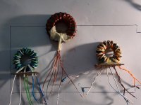
Secondary recitification + common mode inductor , Voltage loop control and overcurrent shutdown.

The last attachment shows the output of the gate drive transformer secondary

Any help to solve the steps in the waveforms are welcome thanks
 

Attachments

  • pic3.jpg
    pic3.jpg
    636.2 KB · Views: 53
Last edited:

MicrosiM

Administrator
Staff member
I would like to see the full project picture.

Gate Drive Transformer picture.

Did you make the GDT yourself?

I can suggest you some tips

Those waves, at witch points of PCB?
 
Hi Microsim I made the GDT myself. Its not yet on pcb but on project board right now with everything soldered. The waves where i mentionned the steps are occuring at the gate of each mosfetpic.jpg

These waves are taken from the GDT secondary pins pic3.jpg

I am still trying to find out whats causing those steps
 

MicrosiM

Administrator
Staff member
OK

my GDT shows same waves at the output without load, I dont think your waves are bad ones.

Your SMPS is working or not?

Wire you have used to make your GDT?

Will show some waves from my GDT today, there are many things affects the performance of the GDT

Thanks
 
More waveforms

Hi Microsim I have made some more test maybe it can help a bit.

1) This is my GDT's secondary unloaded: ADS00002.jpg

2) And this is my ic signal versus my GDT secondary signal unloaded: ADS00003.jpg
 

MicrosiM

Administrator
Staff member
That wave from the Gate drive transformer is normal.

Its only a few things to try out, so it may improve it a bit. But its good wave

Will show today some waves
 

CobraNet

Member
If you´re driving mosfets then you simply can´t. It is caused by charging the D-G capacitance which is multiplied by the change in drain voltage. More info here http://www.irf.com/technical-info/appnotes/mosfet.pdf mostly on page 11
...unless that graph isn´t actually the miller charge effect but some effect of shoot-through.

I saw many designs driving IGBTs / Mosfets with Gate drive transformer without any problems. That is miller effect for sure.

Just explain more why I cant drive Mosfets with transformers ((@ , while its the best method

Read here:- it proves what I am saying :D
 
Last edited:
Lol for sure you can drive Mosfets with a transformer otherwise the term isolated gate drive wouldn't even exist. to come back down to earth, i am thinking of two possible solutions to solve this 1) tuning at the secondary side of the GDT i.e. restoring the square wave as close as possible to original or otherwise (maybe and) add some more deadtime through the TL494. i think i would end up with a combination of both most probably. But i need help with the squarewave restoration
 

MicrosiM

Administrator
Staff member
GDT Results

@ Zeus

I have mad some tests for you, with many GDT I have, see below pictures

Toroidal pictures for GDT I made my self. with core from CWS with AL/nH 5400, yes you need t least this AL/Nh to get same waves

CCF is a GDT from Coil Craft
CRW is a GDT from Crown Amplifier

See and compare them.

Results I am showing here cannot be found any where.

Your wave is OK, and normal, you may need a better core, or bifilar windings, Trifilar windings

DSC000 is the wave ACROSS E+G of IGBT while SMPS is WORKING
 

Attachments

  • DSC01464.jpg
    DSC01464.jpg
    193 KB · Views: 73
  • DSC01466.jpg
    DSC01466.jpg
    185.5 KB · Views: 75
  • DSC01465.jpg
    DSC01465.jpg
    162.1 KB · Views: 94
  • CCF.rar
    43.8 KB · Views: 123
Hi Microdesign thanks a real lot for all your test and pics. I will recheck my GDT core AL/nH value. But effectively thanks to your efforts i can tell the waveform is almost similar to yours. My only question is how i can get a clean signal on the secondary and avoid any cross conduction of the mosfets. Do you have any implementation that you could show your isolated gate drive in case you don't mind. Thanks
 

MicrosiM

Administrator
Staff member
Hi Microdesign thanks a real lot for all your test and pics. I will recheck my GDT core AL/nH value. But effectively thanks to your efforts i can tell the waveform is almost similar to yours. My only question is how i can get a clean signal on the secondary and avoid any cross conduction of the mosfets. Do you have any implementation that you could show your isolated gate drive in case you don't mind. Thanks

Let me know what you need exactly

My tests was done long time ago, that was the driving circuit, same as yours.


See below pictures, hope it helps
 

Attachments

  • DSC01305.jpg
    DSC01305.jpg
    218.8 KB · Views: 87
  • DSC01308.jpg
    DSC01308.jpg
    150.5 KB · Views: 81
  • DSC01136.jpg
    DSC01136.jpg
    222.3 KB · Views: 78
  • DSC01137.jpg
    DSC01137.jpg
    193.1 KB · Views: 67
Hi Microdesign thanks a lot for the quick reply. Actually am looking for the circuit to connect the GDT secondary to Mosfet that you have used and compare it to mine. Can you show me that part of your circuit if you don't mind. This SMPS is for personal use by the way not commercial or anything. Thanks. You can even mail me the schematic of your smps if you wish its mainly for comparison and learning
 
Deadtime versus current sense output

Hi i've made some measurements for deadtime effect on gate drive and current sense. Are the steps in my gate drive waveform related to the current i circled in my current sense output?pic.jpg Thanks
 
CKT and GDT pics here you go

Hi Microsim, here is the pic of the SMPS and this is for the GDT. Its still on proto board till it works i will transfer it to pcb once operational.


CKT.jpg gate transfo.jpg
 

MicrosiM

Administrator
Staff member
Zeus

At this stage, I advice you to make a new SMPS with some help from me, from scratch.

I can give you some guide lines for the New SMPS.

I really cant expect things with that messy PCB, Your PCB looks not so good to me, And you should take care when you make SMPS.

You NEED a toroidal core for BEST results with GDT. try locating some around you.

Let me know what do u think
 
Hi Microsim yes it does look messy i do agree but there's no other solution than going this route until i get it working and then i can lay it down properly on pcb. I would still like to get this design working and it is a working design maybe more annoying than others i don't mind. Could you please tell me what is the part number for your GDT core and is the permeability close to those used in PC PSU forward mode inductor rings? I will consider relaying the compomemts porperly on the protoboard. I would like at least to get that gate waveform shaped properly i can then layout the power components properly.Thanks
 
Last edited:

MicrosiM

Administrator
Staff member
GDT Cores

Hi Microsim yes it does look messy i do agree but there's no other solution than going this route until i get it working and then i can lay it down properly on pcb. I would still like to get this design working and it is a working design maybe more annoying than others i don't mind. Could you please tell me what is the part number for your GDT core and is the permeability close to those used in PC PSU forward mode inductor rings? I will consider relaying the compomemts porperly on the protoboard. Thanks

I will try to show you the schematic i am using for GDT

This is my GDT cores :- http://www.cwsbytemark.com/index.php?main_page=206_221&cPath=206_221&main_page=index

Any one with Al/nH more than 3000 is robust

I purchased these long time ago..

1 x F-114-J = $2.25
1 x F-114-W = $2.25

I think your GDT is the problem, but you didnt told
your SMPS is working or not?

How did you test it?
 
Top