Instructions about adjustment to your Dx Blame MKIII-Hx
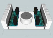
I am uploading video about...but here you have some images attached.
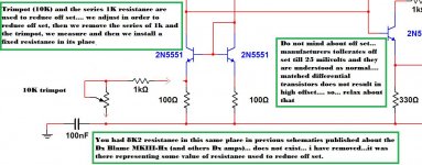
A new updated schematic is attached too, the 8K2 resistance was removed, as it was there to adjust off set only...in the reality it does not belongs to the schematic...some guys may use if needed, others will not.
When differential pair has matched transistors we do not have huge off set.... manufacturers accept off set up to 25 milivolts...and 300 milivolts of off set (huge one) represents only 11 miliwatts (0.011W) and this is nothing, or half of anything..will not move your speaker, will not harm your amplifier, will not produce sound when you power your amplifier on..so..do not worry.....BUT..if you want, you can fix and images shows how to do that.
You will see that Miller capacitor, the compensation one is 56 pf in the schematic....not correct, this is for future tuning and i will have to show you a safe way to do that without destroy your power output transistors...use 180pf as before.
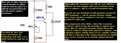
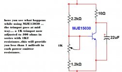
Bias transistor can be anyone you find in your junk box...the plastic ones (material that has plasticity, not real plastic) are insulated and does not need washer, insulator and all that stuff is absent..not needed for them..so, it is more better..... transistor there will face (bias circuit) a few miliamperes and 2.2 volts..power there is very small..also voltage there is 2.2 volts as i said.... any transistor will fit...BUT.... each transistor has it's proper gain..so, the base to emitter resistance network should need adjustments in order to achieve the correct bias for this transistor that will supply 2.2 volts to bias the drivers and output trainees.
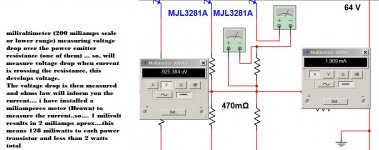
Bias point, or bias current, suggested, must be very low..in order to keep heatsinks cool while in stand by mode.... 1 milivolt measured as voltage drop across the power emitter resistances is all you need...of course you can change this in order to follow your ideas and beliefs....it is up to you..but you gonna be responsible for that..not uncle charlie.
The bias transistor is also a thermal compensating device...when heatsinks goes hot, then this transistor goes hot too..when it is hot its internal resistance drops down.... so, the previous 2.2 volts adjusted (from coletor to emitter) will be no more 2.2 volts..it will reduce...in the reality, when hot, your amplifier will show you much more current in stand by mode..and bias transistor will help to control that for you ..please, do not adjust your amplifier while hot..because when it return to a cool operation it will be underbiased or will have output transistors off, operating as class B, and this distorts low level signals.
I hope this helps.
regards,
Carlos
[video]I am uploading video about...but here you have some images attached. A new updated schematic is attached too, the 8K2 resistance was removed, as it was there to adjust off set only...in the reality it does not belongs to the schematic...some guys may use if needed, others will not. When differential pair has matched transistors we do not have huge off set.... manufacturers accept off set up to 25 milivolts...and 300 milivolts of off set (huge one) represents only 11 miliwatts (0.011W) and this is nothing, or half of anything..will not move your speaker, will not harm your amplifier, will not produce sound when you power your amplifier on..so..do not worry.....BUT..if you want, you can fix and images shows how to do that. You will see that Miller capacitor, the compensation one is 56 pf in the schematic....not correct, this is for future tuning and i will have to show you a safe way to do that without destroy your power output transistors...use 180pf as before. Bias transistor can be anyone you find in your junk box...the plastic ones (material that has plasticity, not real plastic) are insulated and does not need washer, insulator and all that stuff is absent..not needed for them..so, it is more better..... transistor there will face (bias circuit) a few miliamperes and 2.2 volts..power there is very small..also voltage there is 2.2 volts as i said.... any transistor will fit...BUT.... each transistor has it's proper gain..so, the base to emitter resistance network should need adjustments in order to achieve the correct bias for this transistor that will supply 2.2 volts to bias the drivers and output trainees. Bias point, or bias current, suggested, must be very low..in order to keep heatsinks cool while in stand by mode.... 1 milivolt measured as voltage drop across the power emitter resistances is all you need...of course you can change this in order to follow your ideas and beliefs....it is up to you..but you gonna be responsible for that..not uncle charlie. The bias transistor is also a thermal compensating device...when heatsinks goes hot, then this transistor goes hot too..when it is hot its internal resistance drops down.... so, the previous 2.2 volts adjusted (from coletor to emitter) will be no more 2.2 volts..it will reduce...in the reality, when hot, your amplifier will show you much more current in stand by mode..and bias transistor will help to control that for you ..please, do not adjust your amplifier while hot..because when it return to a cool operation it will be underbiased or will have output transistors off, operating as class B, and this distorts low level signals. I hope this helps. regards, Carlos [/video]
")